Page 12
Page 33
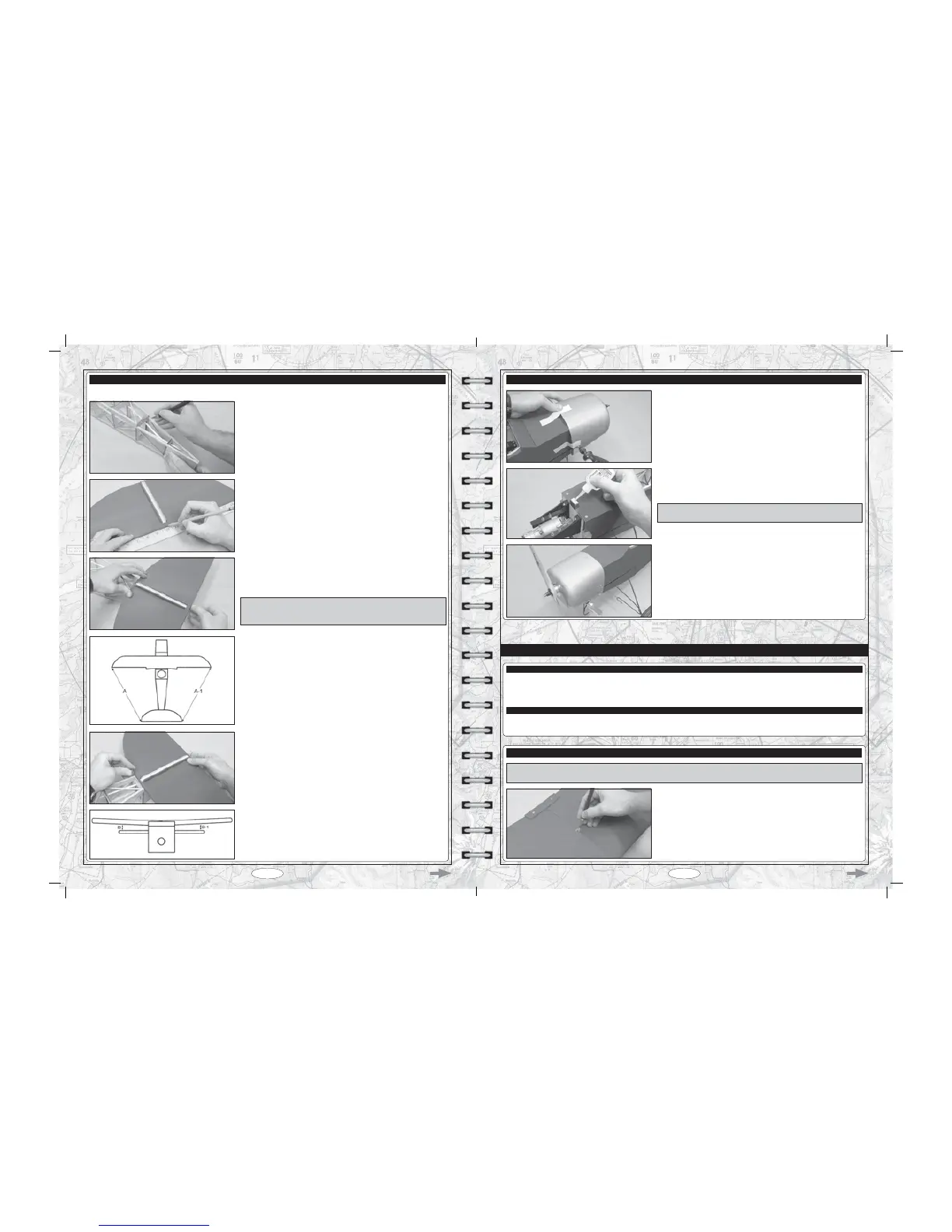
T Measure and draw a centreline on the trailing edge of the stabiliser.
T Set the stabiliser onto the stabiliser mounting platform, push it forward as far as
possible, then line up the centreline you drew on the stabiliser with the centreline
of the back of the fuselage and hold only the trailing edge of the stabiliser in
position, using a T-Pin.
IMPORTANT The front of the stabiliser should be able to pivot slightly
IURPVLGHWRVLGHDQGWKHEDFNVKRXOGVWD\¿UPO\LQSODFHDQGDOLJQHG7KH
trailing edge should not be allowed to move from side to side.
T With the wing mounted to the fuselage, use a ruler to measure the distance
between the tips of the stabiliser and the tips of the wing. Pivot the front of the
stabiliser until both of these measurements are equal.
When both of these measurements are equal, you're assured that the
stabiliser is square to the wing.
T :KHQ\RXUHVDWLV¿HGWKDWWKHVWDELOLVHULVVTXDUHWRWKHZLQJXVHD73LQ
WRKROGWKHIURQWRIWKHVWDELOLVHU¿UPO\LQSODFHDQGDOLJQHG
T Cut away the covering material from the top of both sides of the stabiliser
mounting platform.
67(3$/,*1,1*7+(+25,=217$/67$%,/,6(5
T Remove the elevator and its hinges from the horizontal stabiliser and set them aside for now.
T Look from the front of the aircraft at both the wing and the stabiliser. When
aligned properly, the stabiliser should be parallel to the wing. If the stabiliser
is not parallel to the wing, you'll need to remove the stabiliser and sand down
WKHKLJKHUVLGHRIWKHVWDELOLVHUPRXQWLQJSODWIRUPXQWLO\RXUHVDWLV¿HGZLWKWKH
alignment.
STEP 4: INSTALLING THE COWL
T :LWKWKHFRZOKHOG¿UPO\LQDOLJQPHQWGULOO¿YHPPGLDPHWHUSLORW
holes through the cowl and into the centre of the cowl mounting blocks.
T 5HPRYHWKHFRZODQGDSSO\DFRXSOHRIGURSVRIWKLQ&$LQWRWKH¿YHSLORW
holes and allow the C/A to fully cure.
IMPORTANT The C/A will harden the surrounding wood, making the
mounting area stronger. Do not omit this procedure.
T Mark and cut out the areas of the cowl necessary to give you access to
\RXUHQJLQHVKLJKDQGORZVSHHGQHHGOHYDOYHVDQGWKHPXIÀHU<RXVKRXOG
also install an in-cowl fueling valve in a convenient location on the side of
WKHFRZOVRWKDW\RXFDQ¿OOWKHIXHOWDQN
T ,QVWDOOWKHFRZOXVLQJ¿YH0[PPÀDQJHKHDGZRRGVFUHZVWKHQLQVWDOO
your propeller.
T # 2 Phillips Head Screwdriver
T Modeling Knife
T (1) Right Wing Strut
T (1) Left Wing Strut
T (1) Flying Wires Mounting Post
T (2) Flying Wires
T (10) M3 x 10mm Machine Screws
T (10) M3 Flat Washers
T Straight Edge Ruler
T Airplane Stand
WING STRUTS AND FLYING WIRES INSTALLATION
YOU'LL NEED THE FOLLOWING PARTS FROM THE KIT:
YOU'LL NEED THE FOLLOWING TOOLS AND SUPPLIES:
STEP 1: INSTALLING THE FLYING WIRES MOUNTING POST
T &XWDZD\WKHFRYHULQJPDWHULDOIURPRYHUWKHÀ\LQJZLUHVPRXQWLQJSRVWKROH
in the top of the wing. The mounting post hole is located on the wing's centreline,
4-1/2" (114mm) behind the leading edge of the wing.
IMPORTANT,I\RXZRXOGOLNHWRPRXQWWKHFDQQRQRQWRWKHZLQJ\RXZLOOQRWEHDEOHWRLQVWDOOWKHÀ\LQJZLUHV2QO\LQVWDOOWKHÀ\LQJ
wires if you don't plan on installing the cannon. Both cannot be mounted at the same time.