Page 6
Page 39
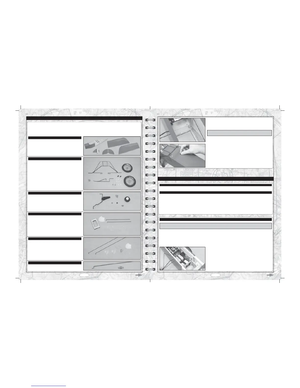
Before you begin assembly, group the parts as we list them below. This will ensure that you have all of the parts before you begin assembly
and it will also help you become familiar with each part.
T (1) Fuselage
T (1) Right Wing Panel with Aileron
T (1) Left Wing Panel with Aileron
T (1) Horizontal Stabiliser with Elevator
T (1) Vertical Stabiliser with Rudder
T (1) Main Landing Gear Bracket
T (1) Nose Skid
T (2) Main Gear Wheels
T (2) Nylon Mounting Brackets (Wide Slot)
T (5) Nylon Mounting Brackets (Narrow Slot)
T (2) Nylon Spacers
T (2) Wheel Collars
T (2) M3 x 5mm Machine Screws
T (13) M3 x 12mm Wood Screws
KIT CONTENTS
AIRFRAME ASSEMBLIES
MAIN LANDING GEAR ASSEMBLY
T (1) Tail Wheel Wire with Mounting Bracket
T (1) Tail Wheel
T (1) Nylon Spacer
T (2) M3 x 5mm Machine Screws
T (3) M3 x 12mm Wood Screws
TAIL WHEEL ASSEMBLY
,)<28),1'$1<3$5760,66,1*25'$0$*('3/($6(&217$&7<285/2&$/02'(/7(&+
'($/(5',5(&7/<86,1*7+(6(3$5$7(&86720(56(59,&(6+((7,1&/8'(':,7+<285.,7
T (2) 32" (813mm) Threaded Wires with 90º Bends
T (2) Nylon Control Horns with Backplates
T (2) Nylon Clevises
T (2) Nylon Snap-Keepers
T (4) M2 x 20mm Machine Screws
T (6) C/A-Style Hinges
ELEVATOR AND RUDDER CONTROL SYSTEMS
T (2) 4-1/2" (114mm) Threaded Wires with 90º Bends
T (1) Plywood Servo Tray
T (2) Nylon Adjustable Control Horns
T (2) Nylon Clevises
T (2) Nylon Snap-Keepers
T (8) C/A-Style Hinges
AILERON CONTROL SYSTEM
T (1) 11-1/2" (292mm) Pushrod Wire with Z-Bend
T (1) Adjustable Pushrod Connector with Nut and Machine Screw
THROTTLE CONTROL SYSTEM
T Glue the balsa hatch latch shim to the front of the hatch frame, making sure
that it's centred.
IMPORTANT7KHKDWFKODWFKVKLPZLOO¿OOWKHQDUURZJDSEHWZHHQWKHKDWFK
ODWFKSLQDQGWKHKDWFKIUDPHKHOSLQJWKHKDWFKFRYHUVWD\¿UPO\LQSODFH
T Install the hatch cover onto the fuselage, checking to make sure that the
KDWFKFRYHULVKHOG¿UPO\LQSODFHE\WKHKDWFKODWFKDWWKHIURQWDQGWKHSO\ZRRG
tab at the rear.
T # 1 Phillips Head Screwdriver
T Modeling Knife
T Scissors
T Electric Drill
T 1/16" (1.6mm) & 5/64" (2mm) Drill Bits
T Straight Edge Ruler
T Pencil
T (1) Decal Set
T Airplane Stand
T Masking Tape
T Heat-Shrink Tubing (for Electric Version)
T Heat Gun (for Electric Version)
T Soldering Iron (for Electric Version)
T Solder (for Electric Version)
FINAL ASSEMBLY
YOU'LL NEED THE FOLLOWING PARTS FROM THE KIT:
YOU'LL NEED THE FOLLOWING TOOLS AND SUPPLIES:
67(3,167$//,1*7+(5(&(,9(5%$77(5<$1'6:,7&++$51(66*/2:9(56,21
T $IWHU\RXYHIRXQGWKH¿QDOORFDWLRQRIWKHUHFHLYHUDQGWKHEDWWHU\PRXQW
them into the fuselage using your favorite method. We mounted the receiver
RQWKHIXVHODJHÀRRULQIURQWRIWKHEDOVDVXSSRUWEXONKHDGDQGPRXQWHGWKH
UHFHLYHUEDWWHU\RQWKHIXVHODJHÀRRULQIURQWRIWKHUHFHLYHU
IMPORTANT This step details the installation of the receiver, battery and switch harness if you're using a glow engine. If you're
using a brushless outrunner electric motor, please skip to step 2 on page 40.
T Wrap the receiver and battery in foam rubber to protect them from vibration. Use a couple strips of masking tape or rubber bands to
hold the foam rubber in place.
Do not wrap the foam rubber too tightly or the vibration dampening quality will be reduced.
T ,QVWDOO\RXUVZLWFKLQWRDFRQYHQLHQWORFDWLRQRQWKHVLGHRIWKHIXVHODJHRSSRVLWH\RXUHQJLQHVPXIÀHU