Page 22
Page 23
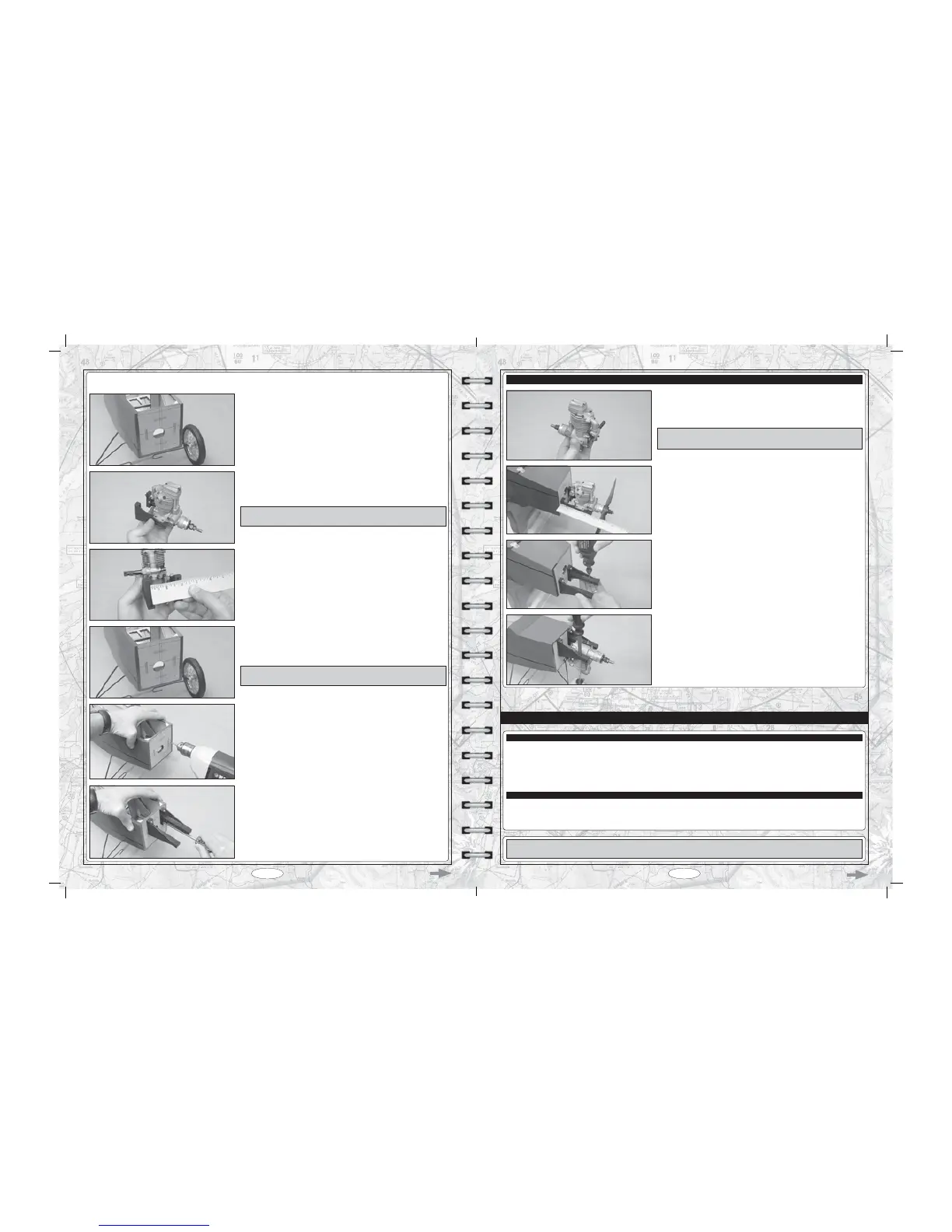
T Measure the distance between the holes in the two engine mounting beams.
As an example, for the Magnum XL .52RFS engine used in this aircraft,
the distance between the holes in the two beams is 1-13/16" (46mm). Your
measurement may differ if you are using a different size engine. It depends on
the width of the engine's crankcase.
T Temporarily glue the two engine mounting beams to your engine's mounting
lugs, using a couple of drops of thick C/A.
IMPORTANT The location of the engine is not important at this time. It's
more important that the beams are square to the mounting lugs.
T Measure and draw a horizontal line 3/16" (5mm) down from the top of the
¿UHZDOOWKHQPHDVXUHDQGGUDZDVHFRQGKRUL]RQWDOOLQHPPGRZQ
IURPWKHWRSRIWKH¿UHZDOO
T 'ULOODPPGLDPHWHUSLORWKROHWKURXJKWKH¿UHZDOODWHDFKRIWKHIRXU
intersecting lines.
T Remove your engine from the engine mounting beams.
T Install the two engine mounting beams, using four M3 x 16mm machine
VFUHZVIRXU0ÀDWZDVKHUVDQGIRXU0EOLQGQXWV)LUPO\WLJKWHQHDFKRIWKH
PDFKLQHVFUHZVWRGUDZWKHEOLQGQXWVLQWRWKHEDFNRIWKH¿UHZDOO
T Divide the measurement found in the procedure above in half, then measure
this resulting distance and draw one line to the right and one line to the left of
the vertical thrust line.
IMPORTANT Make sure to measure from the vertical thrust line, not the
vertical centreline.
T Carefully remove the hatch cover from over the fuel tank compartment and set is aside for now. It's held in place with double-sided
tape from the factory.
T Temporarily install your propeller onto your engine's crankshaft, using the
propeller washer and nut included with your engine.
T Set your engine onto the engine mounting beams, then measure the distance
IURPWKH¿UHZDOOWRWKHEDFNHGJHRIWKHSURSHOOHUDWWKHKXE$GMXVWWKHGHSWK
of the engine so that the measurement is 4-1/2" (114mm).
T Mark the locations of the engine mounting holes onto the engine mounting
beams.
T Remove the engine and drill 5/64" (2mm) diameter pilot holes through the
engine mounting beams at the marks you drew, then enlarge the pilot holes,
using a 1/8" (3mm) diameter drill bit.
T Install the engine onto the engine mounting beams using four M3 x 25mm
VRFNHWFDSVFUHZVHLJKW0ÀDWZDVKHUVDQGIRXU0ORFNQXWVWKHQUHLQVWDOO
the nose skid.
STEP 3: INSTALLING YOUR ENGINE
T If you're using a 4-stroke engine, rotate your engine's carburetor so that the
throttle arm is on the left side of the engine. Refer to your engine's User Guide
for more information.
IMPORTANT The throttle arm must be toward the outside of the engine so
that the throttle pushrod can be installed without interfering with the fuel tank.
T # 2 Phillips Head Screwdriver
T Modeling Knife
T Scissors
T (1) 240cc Fuel Tank
T (3) Aluminium Tubes
T (1) Rubber Stopper
T (1) Metal Plate - Small
T (1) Metal Plate - Large
T (1) Fuel Pick-up (Clunk)
T (1) Silicone Fuel Tubing
T (1) Metal Support Ring
T (1) M3 x 20mm Machine Screw
T Straight Edge Ruler
T Pencil
T 220 Grit Sandpaper
FUEL TANK INSTALLATION - GLOW VERSION
YOU'LL NEED THE FOLLOWING PARTS FROM THE KIT:
YOU'LL NEED THE FOLLOWING TOOLS AND SUPPLIES:
IMPORTANT This section details the installation of the fuel tank for a glow engine. If you are using a brushless outrunner electric
motor, please skip to the Elevator Control System Installation section on page 27.