Page 8
Page 37
T 30 Minute Epoxy
T Modeling Knife
T Straight Edge Ruler
T Pencil
T 220 Grit Sandpaper with Sanding Block
T (1) Right Wing Panel with Aileron
T (1) Left Wing Panel with Aileron
T (2) Hardwood Wing Joiners
T Paper Towels
T Rubbing Alcohol
T Epoxy Mixing Sticks
T Epoxy Mixing Cups
WING ASSEMBLY
YOU'LL NEED THE FOLLOWING PARTS FROM THE KIT:
YOU'LL NEED THE FOLLOWING TOOLS AND SUPPLIES:
T (1) Plywood Wing-Screw Doubler
T (2) M5 x 65mm Nylon Wing Screws
T (2) Hardwood Wing Joiners
T (1) Cannon Mount
T (1) Plastic Cannon Halves
MISCELLANEOUS WING PARTS
T (1) Plywood Hatch Frame
T (3) Plywood Hatch Cover Reinforcement Plates
T (1) Balsa Hatch Latch Shim
T (1) Hatch Latch
BATTERY HATCH ASSEMBLY - ELECTRIC VERSION
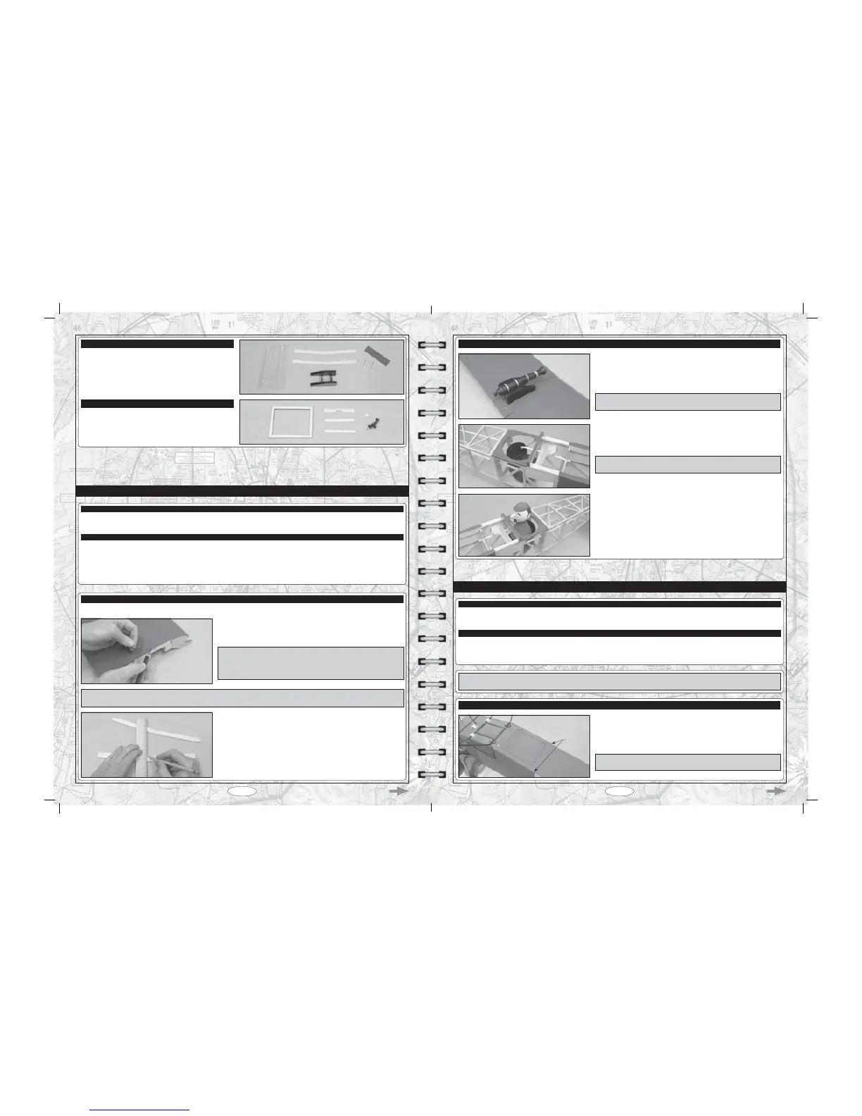
STEP 1: ALIGNING THE WING PANELS
T Cut away the excess covering material that overlaps onto the root ribs of
each wing panel, leaving about 1/16" (1.6mm) overlapped so it does not
pull away.
IMPORTANT It's very important to the integrity of the wing centre-section
joint that you remove as much covering material from the root ribs as
possible. Do not omit this procedure or the wing centre-section joint may
IDLOGXULQJÀLJKW
T Locate and draw a vertical centreline on one side of each of the two wing
joiners.
IMPORTANT There are two wing joiners that support the wing panels. The larger wing joiner is the forward wing joiner and the
smaller wing joiner is the rear wing joiner.
T Remove the aileron and hinges from each of the two wing panels and set them aside for now.
STEP 3: INSTALLING THE CANNON AND PILOT FIGURE
T 7HVW¿WDQG JOXH WKH VHDW EDUUHO RQWR WKH WZR SUHLQVWDOOHG DQJOHG EDOVD
PRXQWLQJEORFNVRQWKHIXVHODJHÀRRU
IMPORTANT You will need to cut a small notch in each side of the seat
barrel backrest to clear the elevator and rudder pushrod guide tubes.
T Glue the cannon into the cannon mount, then align and glue the cannon
mount to the top of the wing. When positioned properly, the back edge of the
cannon mount should be pushed up against the front edge of the wing-screw
doubler and the cannon mount should be centred over the wing's centreline.
IMPORTANT Remember to cut away the covering material from the gluing
surfaces to ensure a strong glue joint.
T *OXHWKHSLORW¿JXUHKHDGWRWKHSLORW¿JXUHERG\WKHQJOXHWKHSLORW¿JXUH
to the top of the seat barrel.
T Thin and Thick C/A
T Modeling Knife
T Straight Edge Ruler
T (1) Plywood Hatch Frame
T (3) Plywood Hatch Cover Reinforcement Plates
T (1) Balsa Hatch Latch Shim
T (1) Hatch Latch
T Pencil
T 220 Grit Sandpaper with Sanding Block
T Airplane Stand
BATTERY HATCH INSTALLATION - ELECTRIC VERSION ONLY
YOU'LL NEED THE FOLLOWING PARTS FROM THE KIT:
YOU'LL NEED THE FOLLOWING TOOLS AND SUPPLIES:
IMPORTANT This section details the installation of the LiPO battery access hatch. If you are using a glow engine, please skip to
the Final Assembly section on page 39.
STEP 1: ASSEMBLING THE HATCH COVER
T Cut out a battery access hatch on the bottom of the fuselage. The hatch
should be 3" (76mm) wide and 3-3/4" (95mm) long. The hatch should be
centred between the fuselage sides and the back edge of the hatch should be
1/2" (13mm) in front of the "step" (A) in each side of the fuselage.
IMPORTANT Use a straight edge ruler and a sharp modeling to ensure
accurate and straight cuts.
A