Page 14
Page 31
T Glue the stabiliser into place, using a generous amount of 30 minute epoxy.
IMPORTANT It's important that the trailing edge of the vertical stabiliser
be even with the back edge of the fuselage and that the vertical stabiliser be
perpendicular to the horizontal stabiliser. Double-check this while the epoxy
is setting up and curing.
T (1) Tail Wheel Wire with Mounting Bracket
T (1) Tail Wheel
T (1) Nylon Spacer
T (2) M3 x 5mm Machine Screws
T (3) M3 x 12mm Wood Screws
T (14) C/A-Style Hinges
HINGING THE CONTROL SURFACES
YOU'LL NEED THE FOLLOWING PARTS FROM THE KIT:
YOU'LL NEED THE FOLLOWING TOOLS AND SUPPLIES:
T 5 Minute Epoxy
T Thin C/A
T C/A Debonder
T # 2 Phillips Head Screwdriver
T Modeling Knife
T Electric Drill
T 5/54" (2mm) and 3/32" (2.4mm) Drill Bits
T Straight Edge Ruler
T Pencil
T 220 Grit Sandpaper with Sanding Block
T T-Pins
T Wax Paper
T Paper Towels
T Rubbing Alcohol
T Epoxy Mixing Sticks
T Epoxy Mixing Cups
T Cut away the covering material from over the precut slot in the root end of
one aileron.
Notice that there is a predrilled hole in the slot to accept the aileron torque
rod wire.
STEP 1: HINGING THE AILERONS
IMPORTANT C/A-style hinges are used to hinge the control surfaces. These hinges are designed to be glued into place using thin
C/A. Do not glue the hinges into place using any other type of glue, such as thick C/A or epoxy. Use of any adhesive other than thin
&$FRXOGUHVXOWLQIDLOXUHRIWKHKLQJHVGXULQJÀLJKW
)RUÀXWWHUIUHHFRQWUROVXUIDFHVDQGFULVSFRQWUROUHVSRQVHLWLVLPSHUDWLYHWKDWWKHKLQJHVEHJOXHGLQSURSHUO\7KLVLVDFKLHYHGE\
having a tight hinge gap (no more than 1/32" (1mm) wide) and using plenty of thin C/A glue. Poor hinge installation can lead to control
VXUIDFHÀXWWHUZKLFKFDQUHVXOWLQDFDWDVWURSKLFIDLOXUHRIWKHDLUIUDPH
PRO TIP The T-Pins will keep the hinges centred and square to the hinge
line while you are hinging the aileron.
T Push two T-Pins through the centre of four aileron hinges.
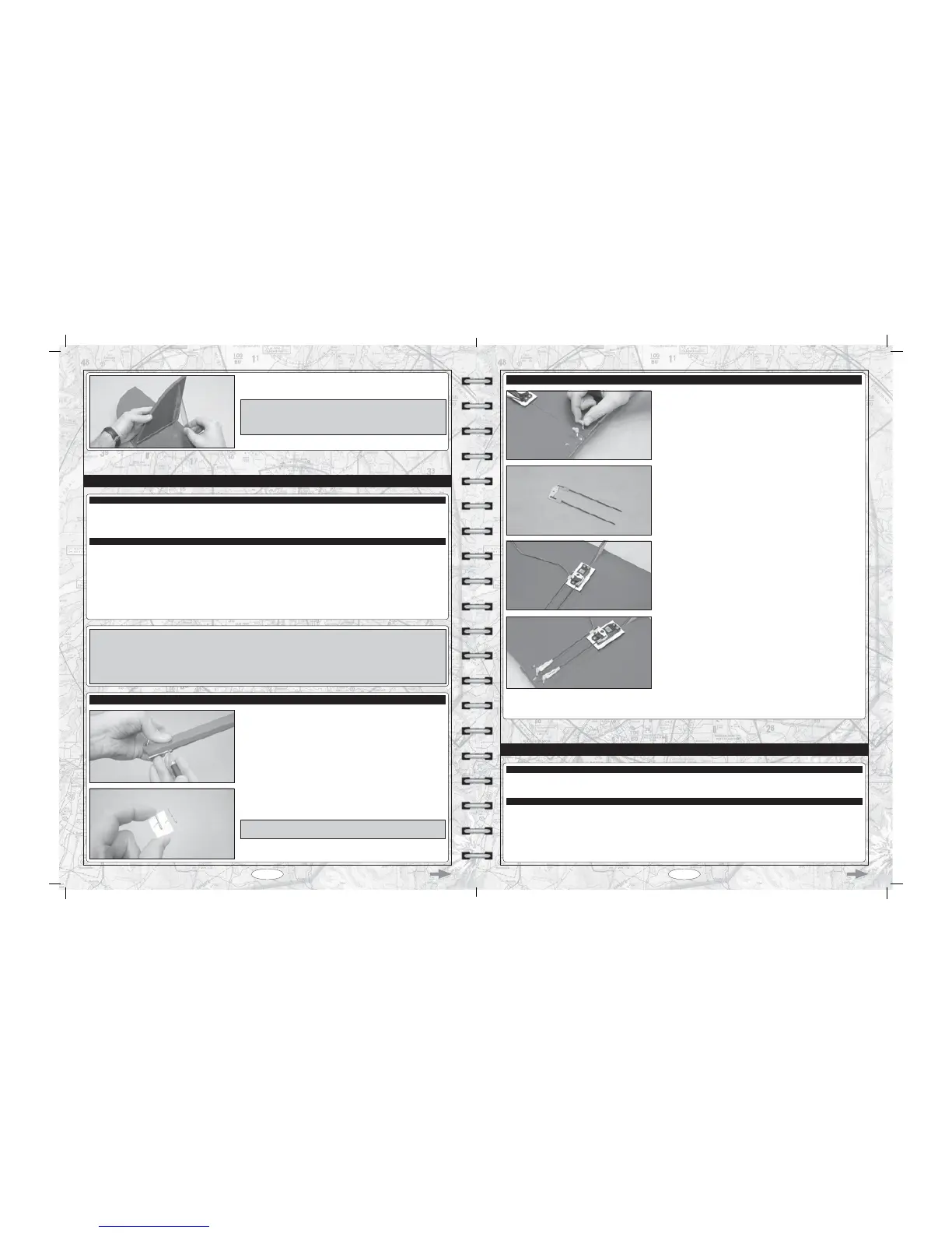
STEP 2: INSTALLING THE AILERON CONTROL LINKAGE ASSEMBLIES
T Thread one adjustable control horn onto each threaded aileron torque
rod. When positioned properly, both adjustable control horns should be even
with the top of the torque rods.
T Cut away two arms from a "4-point" servo horn, then enlarge the hole in
each servo arm that is 5/8" (16mm) out from the centre of the servo horn, using
a 5/64" (2mm) diameter drill bit.
T Install the 90º bend in each pushrod wire into the hole that you enlarged in
the servo arms, using two snap-keepers.
The pushrod wires should be orientated on top of the servo arms.
T Use a couple of pieces of masking tape, taped between the ailerons and
the wing, to hold the ailerons centred.
T With both the aileron servo and the ailerons centred, thread a clevis onto
each pushrod wire and snap the clevises into the adjustable control horns.
T Remove the masking tape and double-check that both the aileron servo horn and both ailerons are still centred. If necessary, thread
the clevises in or out to centre the ailerons, then move the ailerons up and down several times to ensure proper movement. Both ailerons
should move smoothly and not bind in any way.
T Thin and Thick C/A
T # 1 Phillips Head Screwdriver
T Adjustable Wrench
T Modeling Knife
T Electric Drill
T 1/16" (1.6mm) and 5/64" (2mm) Drill Bits
T (1) Cowl
T (5) Cowl Mounting Blocks
T (7) M2 x 10mm Flange-Head Wood Screws
T Straight Edge Ruler
T Pencil
T Rotary Tool with Cutting Disc and Sanding Drum
T 220 Grit Sandpaper with Sanding Block
T Masking Tape
COWL INSTALLATION
YOU'LL NEED THE FOLLOWING PARTS FROM THE KIT:
YOU'LL NEED THE FOLLOWING TOOLS AND SUPPLIES:
T Centre the aileron servo, then install the servo horn onto the servo, making
sure that the servo horn is centred.
T Install the servo horn retaining screw to secure the servo horn to the servo.