Page 34
Page 11
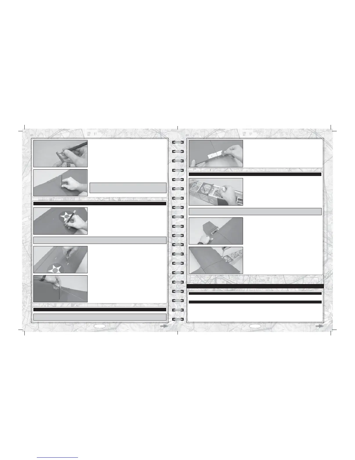
T &XWDZD\ WKH FRYHULQJ PDWHULDO IURP RYHU WKH VORW LQ RQH HQG RI WKH À\LQJ
wires mounting post.
T *OXHWKHÀ\LQJZLUHVPRXQWLQJSRVWLQWRWKHZLQJPDNLQJVXUHWKDWLWVDOLJQHG
straight when viewed from both the front and the side, and that the slot in the top
RIWKHÀ\LQJZLUHVPRXQWLQJSRVWLVSDUDOOHOZLWKWKHOHDGLQJHGJHRIWKHZLQJ
IMPORTANT:KHQ\RXLQVWDOOWKHÀ\LQJZLUHVPRXQWLQJSRVWWKHVORWLQWKH
WRSRIWKHÀ\LQJZLUHVPRXQWLQJSRVWVKRXOGEHSDUDOOHOZLWKWKHOHDGLQJHGJH
of the wing.
STEP 2: INSTALLING THE FLYING WIRES
T &XW DZD\WKHFRYHULQJPDWHULDO IURP RYHU WKH IRXUÀ\LQJZLUHVPRXQWLQJ
holes in the top of the wing. Two holes are located in each half of the wing,
20" (508mm) out from the centreline of the wing. The two forward holes are
located 7" (178mm) in front of the aileron hinge line and the two rear holes
are located 2-3/4" (70mm) in front of the aileron hinge line.
T 0RXQWHDFKHQGRIWKHVKRUWHUÀ\LQJZLUHWRWKHIRUZDUGKROHLQHDFKKDOI
RIWKHZLQJXVLQJWZR0[PPPDFKLQHVFUHZVDQGWZR0ÀDWZDVKHUV
T 0RXQWHDFKHQGRIWKHORQJHUÀ\LQJZLUHWRWKHUHDUKROHLQHDFKKDOIRIWKH
ZLQJXVLQJWZR0[PPPDFKLQHVFUHZVDQGWZR0ÀDWZDVKHUV
IMPORTANT7ZRGLIIHUHQWOHQJWKÀ\LQJZLUHVDUHLQFOXGHG7KHORQJHUÀ\LQJZLUHLVLQVWDOOHGEHWZHHQWKHWZRUHDUKROHVLQWKHZLQJDQG
WKHVKRUWHUÀ\LQJZLUHLVLQVWDOOHGEHWZHHQWKHWZRIRUZDUGKROHVLQWKHZLQJ
T &DUHIXOO\SXOOHDFKRIWKHÀ\LQJZLUHVXSDQGLQWRWKHVORWLQWKHWRSRIWKH
À\LQJZLUHVPRXQWLQJSRVW
STEP 3: INSTALLING THE WING STRUTS
IMPORTANT7KHZLQJVWUXWVZLOO¿WRQO\RQHZD\:KHQLQVWDOOHGWKHVKRUWHUOHQJWKSRUWLRQRIHDFKZLQJVWUXWVKRXOGEHWRZDUG
the leading edge of the wing and the longer length portion of each wing strut should be toward the trailing edge of the wing.
T Cut away the covering material from inside the outline you drew, then glue
the wing-screw doubler onto the wing using thick C/A.
STEP 2: MOUNTING THE WING
T Apply a couple of drops of thin C/A into each of the two threaded wing-screw
mounting holes in the fuselage. Allow the C/A to fully cure before proceeding.
IMPORTANT The C/A will soak into the plywood, strengthening the threads. Do not omit this procedure. Allow the C/A to fully cure
before proceeding.
T Place the wing into the wing saddle, push it forward completely, then push
the trailing edge down into place.
T Align the holes in the wing with the threaded holes in the wing mounting
block inside the fuselage.
T Secure the wing into place, using two wing mounting screws.
Don't overtighten the screws. You don't want to crush the wing or break
the screws off.
T (1) Horizontal Stabiliser with Elevator
T (1) Vertical Stabiliser with Rudder
STABILISER INSTALLATION
YOU'LL NEED THE FOLLOWING PARTS FROM THE KIT:
YOU'LL NEED THE FOLLOWING TOOLS AND SUPPLIES:
T 30 Minute Epoxy
T Modeling Knife
T Straight Edge Ruler
T Pencil
T Builder's Triangle
T 220 Grit Sandpaper with Sanding Block
T Paper Towels
T Rubbing Alcohol
T Epoxy Mixing Sticks
T Epoxy Mixing Cups