Page 24
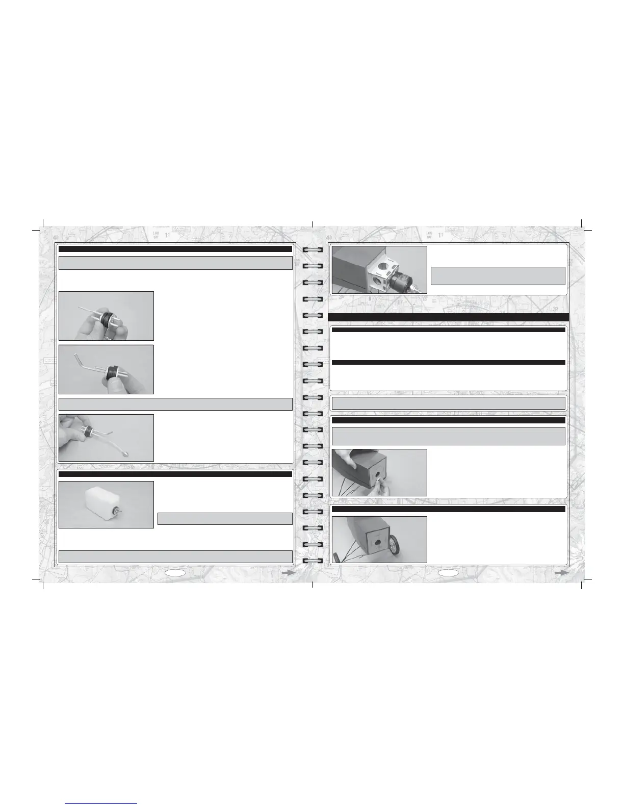
Page 21
STEP 1: ASSEMBLING THE RUBBER STOPPER
IMPORTANT Discard the shortest aluminium tube. It will not be used if you're using an in-cowl fueling valve as suggested. If you
GRQWXVHDQLQFRZOIXHOLQJYDOYHXVHWKHVKRUWHVWDOXPLQLXPWXEHDVWKH¿OOWXEH
T Use 220 grit sandpaper to lightly sand away any burrs that might be on the ends of the two aluminium tubes.
T Push the two aluminium tubes through the rubber stopper.
T Push the two aluminium tubes through the rubber stopper.
T Slide the large diameter metal plate over the tubes at the front of the rubber
stopper, and slide the small diameter metal plate over the tubes at the rear of
the rubber stopper.
T Measure the distance that the two aluminium tubes protrude from the front
of the stopper assembly. This distance should be 3/8" (10mm).
T Carefully bend the longer of the two aluminium tubes up at a shallow angle,
being careful not to kink the tubing as you bend it.
IMPORTANT When the stopper assembly is installed in the fuel tank, the top of the vent tube (the tube you just bent) should rest just
below the top of the fuel tank. The top of the fuel tank is a longer distance from the fuel tank opening than the bottom is.
T Secure one end of the silicone fuel tubing onto the end of the clunk.
T Slide the silicone fuel tubing, with the clunk attached, onto the end of the
aluminium fuel pick-up tube (straight tube). Adjust the length of the silicone
tubing until the end of the clunk is 3-1/4" (83mm) back from the rear of the
stopper assembly.
T Push the metal neck-reinforcement ring over the neck of the fuel tank
opening, then carefully push the stopper assembly into the fuel tank and rotate
it until the aluminium vent tube rests just below the top of the fuel tank. When
VDWLV¿HGZLWKWKHDOLJQPHQWLQVWDOODQGWLJKWHQWKH0[PPPDFKLQHVFUHZ
until the rubber stopper expands and seals the fuel tank opening.
IMPORTANT The top of the fuel tank is a longer distance from the fuel
tank opening than the bottom.
STEP 2: INSTALLING THE RUBBER STOPPER ASSEMBLY
T With the stopper assembly installed, double-check to make sure that the clunk can move freely inside the fuel tank. Ideally, the clunk
should be about 1/4" (6mm) in front of the back of the fuel tank. This will ensure that the clunk can't get stuck in the fuel tank during
ÀLJKW$OVRGRXEOHFKHFNWKDWWKHHQGRIWKHYHQWWXEHLVMXVWEHORZWKHWRSRIWKHIXHOWDQN
PRO TIP Holding the fuel tank up to a bright light will allow you to see inside to double-check the correct position of the clunk and
the vent tube.
T After the epoxy sets up, glue one balsa triangle support between each side
RIWKHPRWRUPRXQWLQJER[DQGWKH¿UHZDOO
IMPORTANT You will need to cut the balsa triangle support that is glued
to the bottom of the motor mounting box shorter so that it doesn't interfere
with the nose skid mounting bracket.
T Thick C/A
T # 2 Phillips Head Screwdriver
T 2.5mm Hex Wrench
T 5.5mm Nut Driver
T (2) Engine Mounting Beams
T (4) Plywood Filler Blocks
T (4) M3 x 25mm Socket-Cap Screws
T (4) M3 x 20mm Machine Screws
T (4) M3 Lock Nuts
T (4) M3 Blind Nuts
T (12) M3 Flat Washers
T Electric Drill
T 5/64" (2mm) and 1/8" (3mm) Drill Bits
T Straight Edge Ruler
T Pencil
ENGINE INSTALLATION - GLOW VERSION
YOU'LL NEED THE FOLLOWING PARTS FROM THE KIT:
YOU'LL NEED THE FOLLOWING TOOLS AND SUPPLIES:
This section details the installation of the Magnum XL .52RFS four-stroke engine. Installation of a two-stroke engine uses the same
techniques. Regardless of what type of engine you use, the engine should be mounted inverted.
T 7HPSRUDULO\UHPRYHWKHQRVHVNLGIURPWKH¿UHZDOODQGVHWLWDVLGH,WZLOO
be easier to align and install the engine without it in place.
T *OXHRQHSO\ZRRG¿OOHUEORFNLQWRHDFKSUHFXWVORWLQWKH¿UHZDOO
STEP 1: INSTALLING THE PLYWOOD FILLER BLOCKS
IMPORTANT<RXPXVWLQVWDOOWKHSO\ZRRG¿OOHUEORFNVDVGHVFULEHGLQWKHSURFHGXUHEHORZ7KHSO\ZRRG¿OOHUEORFNVZLOOSUHYHQW
exhaust residue from getting inside the fuselage and, depending on the size of your engine, the mounting holes may be located right
QH[WWRRUHYHQLQVLGHWKHVORWV,QVWDOOLQJWKH¿OOHUEORFNVHQVXUHVWKDWWKHHQJLQHPRXQWLQJDUHDZLOOEHVWURQJHQRXJK
STEP 2: INSTALLING THE ENGINE MOUNTING BEAMS
T 0HDVXUHDQGGUDZDYHUWLFDOFHQWUHOLQHRQWKH¿UHZDOO
T Next, measure and draw a vertical line 1/8" (3mm) to the right of the
centreline you just drew. This will be the vertical thrust line and will be used to
line up the engine from side-to-side.