11MCP15-500.9
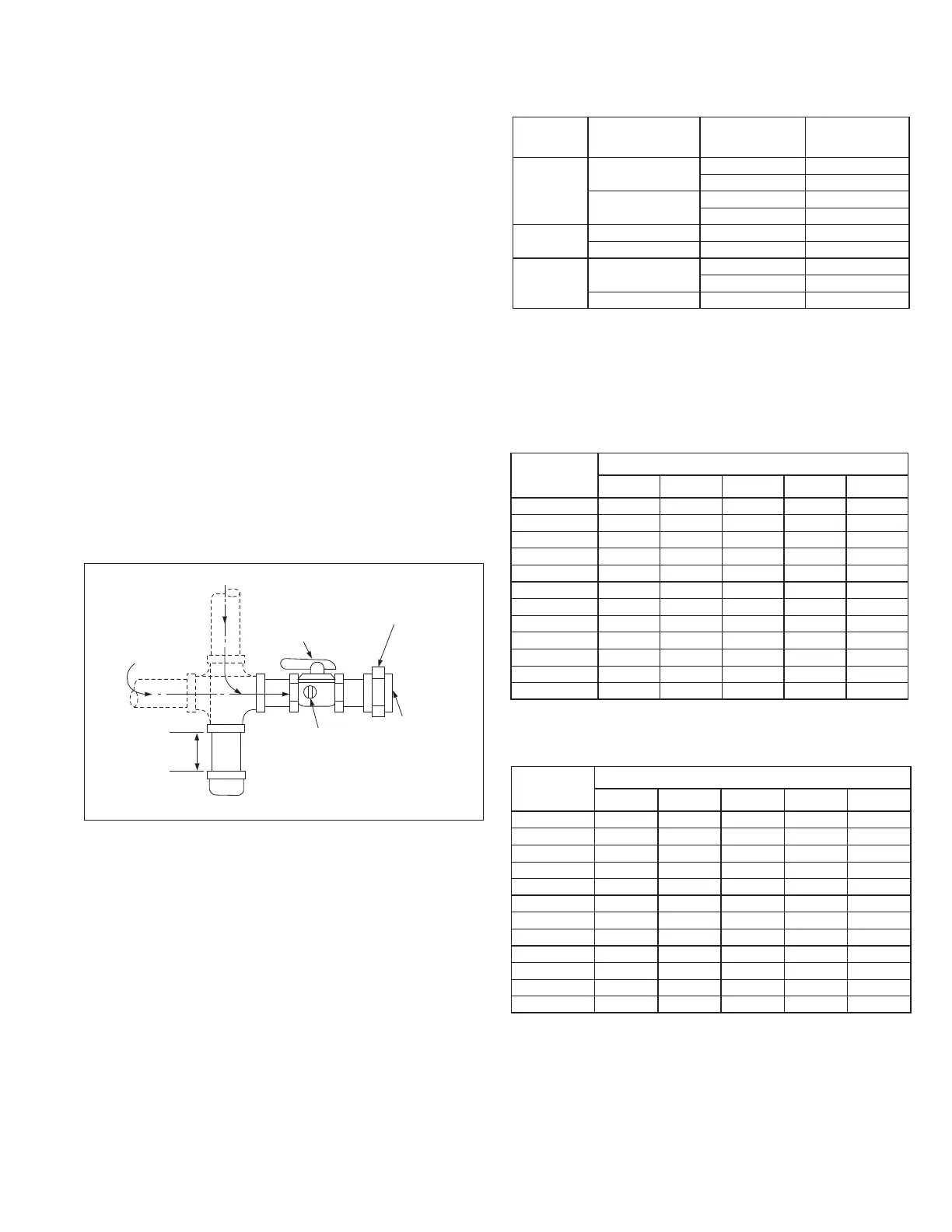
Figure 11.1 - Recommended Sediment Trap/Manual
Shut-off Valve Installation
GAS
SUPPLY LINE
GAS
SUPPLY LINE
GROUND JOINT
UNION WITH
BRASS SEAT
MANUAL GAS
SHUT-OFF VALVE
3"
MIN.
SEDIMENT
TRAP
PLUGGED
1/8" NPT TEST
GAUGE CONNECTION
TO GAS
CONTROLS
j Valve is in the “OFF” position when handle is perpendicular to pipe.
GAS CONNECTIONS
W.C. for propane gas and should not drop below 6.0" W.C.
when the unit is operating. When sizing the inlet gas pipe
diameter, make sure that the unit supply pressure can be
met after the 0.3" or 0.5” W.C. has been subtracted. If the
pressure drop is too high, refer to NFPA 54 National Fuel
Gas Code for other pipe capacities.
3. The gas piping is to enter the unit from the side (refer to
the unit dimensions). B- and C-Cabinet sized units include
a hole and grommet in the side of the casing for side gas
piping entry. D-Cabinet sized units include two holes with
grommets for side pipe entry. Install a ground joint union
with brass seat and a manual shut-off valve external of the
unit casing, and adjacent to the unit for emergency shut-
off and easy servicing of controls, including a 1/8" NPT
plugged tapping accessible for test gauge connection (see
Figure 11.1). Verify the manual shut-off valve is gas tight
on an annual basis.
4. Provide a sediment trap before each unit in the line where
low spots cannot be avoided (see Figure 11.1).
5. When Pressure/Leak testing pressures above 14" W.C.
(1/2 psi), close the field installed shut-off valve, disconnect
the appliance and its combination gas control from the gas
supply line, and plug the supply line before testing. When
testing pressures 14" W.C. (1/2 psi) or below, close the
manual shut-off valve on the appliance before testing.
Table 11.1 - Gas Heating Piping Connection Sizes
j Units with Natural Gas heating option have model nomenclature Digit 17 = 2
or 3. Units with Propane (LP) Gas heating option have model nomenclature
Digit 17 = 5 or 6.
k C-Cabinet units consist of two furnaces that together total the value shown in
Table 11.1.
l D-Cabinet units consist of two furnaces that together total the value shown in
Table 11.1 for sizes up to 800,000 Btu/hr. For sizes over 800,000 Btu/hr, the
unit consists of four furnaces that together total the value shown in Table 11.1.
n Capacities based on gas pressure up to 14" W.C. through Schedule 40 pipe
with a pressure drop of 0.5" W.C. for Propane gas with a specific gravity of
1.50.
Table 11.2 - Natural Gas Pipe Capacities (MBH) m
Pipe Length
(ft)
Nominal Gas Pipe Diameter
1” 1-1/4” 1-1/2” 2” 2-1/2”
10 540 1,113 1,659 3,203 5,103
20 371 762 1,145 2,195 3,507
30 298 612 917 1,764 2,814
40 255 524 784 1,512 2,405
50 226 464 695 1,344 2,132
60 205 420 630 1,218 1,932
80 175 360 540 1,038 1,659
100 155 319 478 921 1,470
125 138 282 423 816 1,302
150 125 256 384 739 1,176
175 114 235 353 680 1,082
200 107 219 329 632 1,008
Pipe Length
(ft)
Nominal Gas Pipe Diameter
1” 1-1/4” 1-1/2” 2” 2-1/2”
10 1,150 2,350 3,520 6,790 10,800
20 787 1,620 2,420 4,660 7,430
30 632 1,300 1,940 3,750 5,970
40 541 1,110 1,660 3,210 5,110
50 480 985 1,480 2,840 4,530
60 434 892 1,340 2,570 4,100
80 400 821 1,230 2,370 3,770
100 372 763 1,140 2,200 3,510
125 349 716 1,070 2,070 3,290
150 330 677 1,010 1,950 3,110
175 292 600 899 1,730 2,760
200 265 543 814 1,570 2,500
Table 11.3 - Propane Gas Pipe Capacities (MBH) n
m Capacities based on gas pressure up to 14” W.C. through Schedule 40 pipe
with a pressure drop of 0.3” W.C. for Natural gas with a specific gravity of 0.60.
Example:
A D-Cabinet unit with Digit 17=2 (Natural Gas) and Digit 18=Q (800MBH)
is installed in a location requiring 50 feet of gas supply pipe. What is the
minimum pipe diameter required for the supply pipe?
From Table 11.2, 50 feet of 1-1/2” pipe has a capacity of 695MBH which may
result in too significant of a pressure drop. The 2” pipe has a capacity of
1,344MBH which is sufficient for a unit with an 800MBH Natural Gas heat option.
Cabinet Size
(Digit 6)
Gas Type
(Digit 17) j
Furnace Size
(MBH)
Gas Connection
Size
B
Natural Gas
Below 200 1/2”
200 and Larger 3/4”
Propane (LP) Gas
Below 300 1/2”
300 and Larger 3/4”
C k
Natural Gas All 1”
Propane (LP) Gas All 3/4”
D l
Natural Gas
Below 850 1” (Qty 2)
850 and Larger 1-1/2” (Qty 2)
Propane (LP) Gas All 1” (Qty 2)