38 MCP15-500.9
UNIT COMPONENT IDENTIFICATION / LOCATION
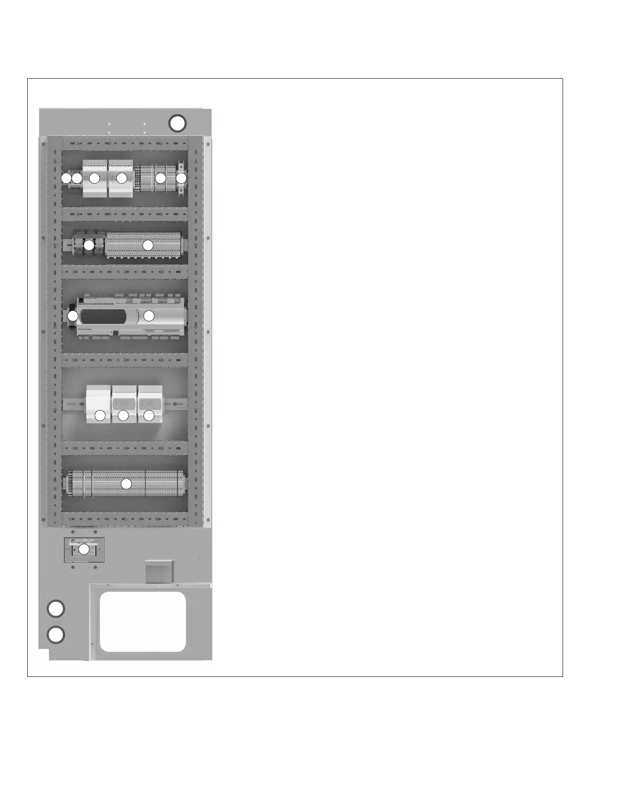
Figure 38.1 - Typical Controls Cabinet - D-Cabinet Sized Units j
1. (O) Remote shutdown relay
2. (O) Supply fan enable relay (for units with two supply fan VFD’s)
3. (S) Carel EVD Ultracap - Circuit #1
4. (S) Carel EVD Ultracap - Circuit #2
5. (S) Low voltage terminal strip
6. (S) Controls secondary circuit breaker
7. (O) Four-pole relays for smoke detector(s) and exhaust fan initiation
8. (S) Low voltage terminal strip
9. (S) Solid state relay unloader
10. (S) Carel PCO5+ microprocessor controller
11. (S) Carel PCOe microprocessor expansion module
12. (S) Carel EVD electronic expansion valve controller - Circuit #1
13. (S) Carel EVD electronic expansion valve controller - Circuit #2
14. (S) Low voltage terminal strip
15. (O) GFCI convenience outlet
(S) = standard (O) = optional
1 3 4 5
11 12
14
13
15
7 8
9 10
62
j Location of components is typical, but may change depending on the configuration of the unit.
Main Panel
Ref: 3H039503