Control Operating Sequence
Unit heaters are supplied with standing pilot control systems
as standard or intermittent pilot systems with continuous retry
as an option. On standing pilot and mechanical modulation
systems the main burner is turned off 100% when the
thermostat is satisfied, but the pilot remains lit. For intermittent
pilot systems, except mechanical modulation both the main
burner and pilot burner are turned off 100% when the
thermostat is satisfied. Standing pilot systems, for both natural
and propane gas, have a manually lit pilot which stays lit until
the gas valve is manually turned to the off position. On a call
for heat, the gas valve opens, sending gas to the burner
allowing the unit to fire. Intermittent pilot systems, for both
natural and propane gas, the ignition controller is 100% shut-off
with continuous retry. On a call for heat, the system will attempt
to light the pilot for 70 seconds. If the pilot is not sensed for any
reason, the ignition control will wait for approximately six
minutes with the combination gas control closed and no spark.
After six minutes, the cycle will begin again. After three cycles,
some ignition controllers lockout for approximately one hour
before the cycle begins again. This will continue indefinitely until
the pilot flame is sensed or power is interrupted to the system.
Refer to table 14.1 for control code descriptions.
NOTE: Gas Control Options could change the listed
sequence of operation based on their function.
The descriptions given are for the basic unit heater.
Single-Stage Gas Controls (standing pilot)
Utilizes a single-stage combination gas control with a standing
pilot operator and a single-stage low voltage thermostat.
1. Pilot is lit continuously.
2. The thermostat calls for heat.
3. The main gas valve is opened and the main burner is lit to
100% full fire.
4. The air mover starts after 30 to 90 seconds.
5. The unit continues to operate until the thermostat is
satisfied, at which time the main valve closes 100%.
6. The air mover stops after 30 to 90 seconds.
Single-Stage Gas Controls (intermittent pilot)
Utilizes a single-stage combination gas, an ignition control, and
a single-stage low voltage thermostat.
1. The thermostat calls for heat.
2. The pilot valve opens and the spark ignitor sparks in an
attempt to light the pilot.
3. Once the pilot is lit, the flame sensor proves the pilot and
stops the spark ignitor from sparking.
4. The main gas valve is opened and the main burner is lit to
100% full fire.
5. The air mover starts after 30 to 90 seconds.
6. The unit continues to operate until the thermostat is satisfied,
at which time both the main and pilot valves close
100%.
13
Table 13.1
Manifold Pressure & Gas Consumption
➀
Natural Propane
BTU/Cu. Ft. 1050 2500 No. of
Model Specific Gravity 0.60 1.53 Orifices
Manifold Pressure In. W.C. 3.5 10.0
CFH 28.6 12.0
PD 30 Gal/Hr. Propane – .33 1
Orifice Drill Size 38 52
CFH 47.6 20.0
Gal/Hr. Propane – .55 1
Orifice Drill Size 30 45
CFH 71.4 30.0
Gal/Hr. Propane – .82 1
Orifice Drill Size 21 39
CFH 95.2 40.0
Gal/Hr. Propane – 1.15 2
Orifice Drill Size 30 45
CFH 119.0 50.0
Gal/Hr. Propane – 1.43 2
CFH 138.1 58.0
Gal/Hr. Propane – 1.64 2
Orifice Drill Size 21 39
CFH 166.7 70.0
Gal/Hr. Propane – 1.86 3
Orifice Drill Size 28 43
CFH 190.5 80.0
Gal/Hr. Propane – 2.19 3
Orifice Drill Size 25 42
CFH 238.1 100.0
Gal/Hr. Propane – 2.74 3
CFH 285.7 120.0
Gal/Hr. Propane – 3.29 4
Orifice Drill Size 21 39
CFH 333.3 140.0
Gal/Hr. Propane – 3.84 5
Orifice Drill Size 23 41
CFH 381.0 160.0
PD 400 Gal/Hr. Propane – 4.38 6
➀ Above gases based on average standards. Units can be
furnished for gases of different values and specific gravities.
(Gal./Hr. based on 60°F. 30" Hg., 91,500 BTU/Gal.) In Canada,
refer to rating plate on side of unit for orifices at high altitude.
START-UP PROCEDURE
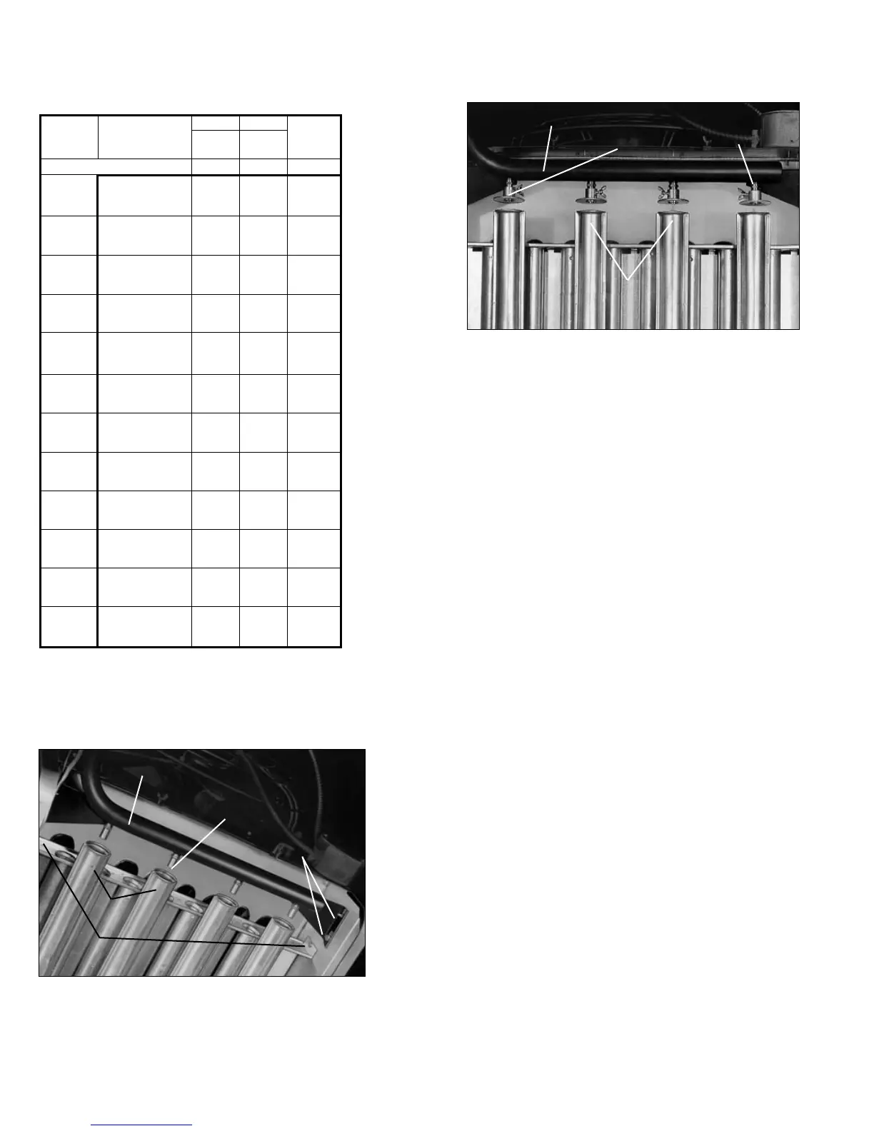
Figure 13.1
Manifold Adjustment, Natural Gas
MANIFOLD
MIXER
TUBES
BURNER
RETAINING PIN
MAIN
BURNER
ORIFICES
MANIFOLD MOUNTING
SCREW AND PIN
Figure 13.2 - Air Shutter Adjustment, Propane Gas
MANIFOLD
MIXER
TUBES
MAIN
BURNER
ORIFICES
AIR
SHUTTER
PD 50
BD 50
PD 75
BD 75
PD 100
BD 100
PD 125
BD 125
PD 150
BD 150
PD 175
BD 175
PD 200
BD 200
PD 250
BD 250
PD 300
BD 300
PD 350
BD 350