4
UNIT LOCATION
Sound and Vibration Levels
All standard mechanical equipment generates some sound and
vibration that may require attenuation. Libraries, private offices and
hospital facilities will require more attenuation, and in such cases,
an acoustical consultant may be retained to assist in the
application. Locating the equipment away from the critical area is
desirable within ducting limitations. Generally, a unit should be
located within 15 feet of a primary support beam. Smaller
deflections typically result in reduced vibration and noise
transmission.
UNIT LIFTING
All standard units are shipped fully boxed. Larger units are also
supplied with skid supports on the bottom of the box. The larger
units may be lifted from the bottom by means of a fork lift or other
lifting device only if the shipping support skids are left in place and
the forks support the whole depth of the unit. If the unit must be
lifted from the bottom for final installation without the carton in
place, be sure to properly support the unit over its entire length
and width to prevent damage. When lifting units, make sure the
load is balanced.
UNIT SUSPENSION
Be sure the method of unit suspension is adequate to support the
weight of the unit (see Weights for base unit and factory installed
option weights). For proper operation, the unit must be installed in
a level horizontal position. Combustible material and service
clearances as specified in Figure 3.1 and Tables 3.2 and 3.3 must
be strictly maintained. To assure that flames are directed into the
center of the heat exchanger tubes, the unit must be level in a
horizontal position. Use a spirit level to ensure that the unit is
suspended correctly.
The most common method of suspending Modine gas unit heaters
is to utilize 3/8” threaded rod. On each piece of threaded rod used,
screw a nut a distance of about one inch onto the end of the
threaded rods that will be screwed into the unit heater. Then place
a washer over the end of the threaded rod and screw the threaded
rod into the unit heater weld nuts on the top of the heater at least
5 turns, and no more than 10 turns. Tighten the nut first installed
onto the threaded rod to prevent the rod from turning. Drill holes
into a steel channel or angle iron at the same centerline
dimensions as the heater that is being installed. The steel channels
or angle iron pieces need to span and be fastened to appropriate
structural members. Cut the threaded rods to the preferred length,
place them through the holes in the steel channel or angle iron
and secure with washers and lock nuts or lock washers and nuts.
A double nut arrangement can be used here instead of at the
unit heater (a double nut can be used both places but is not
necessary). Do not install standard unit heaters above the
maximum mounting height shown in tables 17.1 or 17.3.
On all propeller units, except sizes 350 and 400, two tapped holes
(3/8-16) are located in the top of the unit to receive threaded rods.
Units with two point suspension, sizes 30 through 300, incorporate
a level hanging feature. Depending on what options and
accessories are being used, the heater may not hang level as
received from the factory. Do not hang heaters with deflector hoods
until referring to the “installation manual for deflector hoods” and
making the recommended preliminary adjustments on the heater.
These preliminary adjustments need to be made with the heater
resting on the floor.
Propeller sizes 30 through 300 units without deflector hoods that
do not hang level after being installed, can be corrected in place.
Simply remove both outer side panels (screws to remove are on
back flange of side panel) and you will see the (adjustable)
mounting brackets (Fig. 4.1). Loosen the set screws holding the
mounting brackets in place and using a rubber mallet or something
similar, tap the heater into a position where the unit hangs level.
Re-tighten set screws and replace the outer side panels.
Propeller sizes 350 and 400 have four mounting holes. On all
blower units, except the 350 and 400, two tapped holes are
provided in the top of the unit and two holes in the blower support
bracket. The 350 and 400 have four tapped holes in the top of the
unit and two in the blower support bracket for mounting.
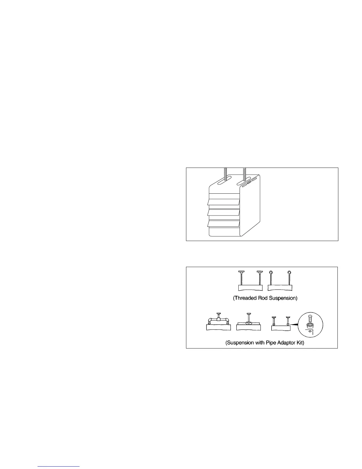
NOTE: A pipe hanger adapter kit, shown in Figure 4.2 is
available as an accessory. One kit consists of two drilled 3/4”
IPS pipe caps and two 3/8 - 13 x 1-3/4” capscrews to facilitate
threaded pipe suspension.
Figure 4.1
Adjustable Mounting Brackets - To Adjust:
Figure 4.2
Suspension Methods
1. Remove outer side panels.
2. “Set screws” - loosen and
position bracket where needed
– then tighten set screws.
3. Re-attach outer side panels.