EasyManua.ls Logo

Modine Manufacturing HD User Manual

Modine Manufacturing HD
224 pages
To Next Page IconTo Next Page
Page #1 background imageLoading...
Page #1 background image
6107.18 • JULY, 2020
GAS-FIRED UNIT HEATERS
RESIDENTIAL, COMMERCIAL & INDUSTRIAL
POWER VENTED
HD, HDB, PDP, BDP, PTP, BTP
SEPARATED COMBUSTION
HDS, HDC, PTS, BTS
HIGH-EFFICIENCY SEPARATED COMBUSTION
PTC, BTC

Table of Contents

Other manuals for Modine Manufacturing HD

Questions and Answers:

Modine Manufacturing HD Specifications

General IconGeneral
BrandModine Manufacturing
ModelHD
CategoryGas Heater
LanguageEnglish

Summary

GAS-FIRED UNIT HEATERS: RESIDENTIAL, COMMERCIAL & INDUSTRIAL

POWER VENTED

Features of Modine's power-vented unit heaters.

SEPARATED COMBUSTION

Features of Modine's separated combustion units.

HIGH-EFFICIENCY SEPARATED COMBUSTION

Features of Modine's high-efficiency separated combustion units.

POWER-EXHAUSTED, PROPELLER UNIT HEATERS

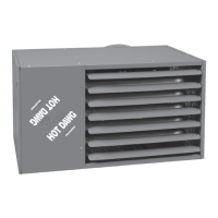
MODEL HD

Features and benefits of the Hot Dawg® HD model.

MODEL PDP

Features and benefits of the PDP model.

MODEL PTP

Features and benefits of the PTP model.

SEPARATED COMBUSTION PROPELLER UNIT HEATERS

MODEL HDS

Features and benefits of the HDS model.

MODEL PTS

Features and benefits of the PTS model.

HIGH-EFFICIENCY CONDENSING UNIT HEATERS

MODEL PTC

Features and benefits of the PTC model.

MODINE CONSERVICORE® HEAT EXCHANGER

Details on the Conservicore® secondary heat exchanger technology.

BLOWER MODELS

MODEL HDB

Features and benefits of the HDB blower model.

MODEL BDP

Features and benefits of the BDP blower model.

MODEL BTP

Features and benefits of the BTP blower model.

STANDARD FEATURES AND FACTORY OPTIONS

Cabinet and Air Mover

Features related to the unit's casing and fan.

Heat Exchanger and Burner

Features of the heat exchange and combustion components.

Controls

Features related to the unit's control system.

HIGH AND LOW INTENSITY INFRARED HEATERS

MODEL IHR

Features and benefits of the IHR model.

MODEL OHP

Features and benefits of the OHP model.

MODEL IPT

Features and benefits of the IPT model.

MODINE BREEZE® ACCUSPEC SIZING & SELECTION PROGRAM

Fast and Simple Unit/Thermostat/Accessory Selection

Overview of the program's unit, thermostat, and accessory selection process.

Submittal Schedules

Information on generating submittal schedules.

INSTALLATION AND SERVICE MANUAL - HIGH INTENSITY GAS FIRED INFRARED UNIT HEATERS

Inspection on Arrival

Steps for checking the unit upon delivery for damage.

Special Precautions

Critical safety measures and warnings for installation.

Unit Location

Guidelines for proper placement of the unit.

Clearances to Combustibles

Hazards Include

Potential hazards related to unit placement near combustibles.

Combustible Items Include

List of items requiring clearance from the unit.

Gas Connection

Standards, Certifications, and Government Regulations

Compliance requirements for gas connections.

Chart 1.2 • Standards and Code Installation Guidelines

Code guidelines for installation aspects.

Heater Placement

Heater Mounting

Figure 5.2 - Unit Heater Turned 180°

Instructions for rotating the unit.

Ventilation

Figure 2.4 • Hot Flue Discharge

Diagram showing proper flue discharge.

Provisions must also be made...

Requirements for fresh air intake and exhaust.

Gas Supply

Important! Before connecting the gas supply...

Pre-connection checks for gas supply.

Chart 2.3 • Manifold Pressure

Required manifold pressures for different gas types.

Electrical Requirements and Wiring Diagrams

Figure 2.6 • Typical Field Wiring

Diagram for common electrical wiring configurations.

Figure 2.7 • Millivolt • 750 Schematic

Wiring diagram for millivolt control systems.

Figure 2.8 • 24 V Schematic

Wiring diagram for 24 VAC systems.

Figure 2.9 • 120 V Schematic

Wiring diagram for 120 VAC systems.

Operation

Direct Spark Ignition

Lighting and shutdown instructions for direct spark ignition.

Millivolt

Lighting and shutdown instructions for millivolt systems.

Maintenance

General Maintenance

Annual maintenance procedures.

Manifold Assembly Removal

Procedure for removing the manifold assembly.

Burner and Pilot Assembly Removal

Procedure for removing the burner and pilot assembly.

Service & Troubleshooting

Pilot does not light

Troubleshooting steps for pilot ignition failure.

Main burners do not light (Pilot is lit)

Troubleshooting steps for main burner failure.

Parts Listing

Chart 4.2 • Direct Spark Control Components

List of control components for direct spark ignition.

Chart 4.3 • Millivolt Control Components

List of control components for millivolt systems.

Limited Warranty

Component Applicable Models

Warranty periods for different parts.

BUYER’S REMEDY FOR BREACH OF WARRANTY

Details on warranty remedies.

YEAR-ROUND COMFORT TO WORK, PLAY AND RELAX

DIMENSIONAL DATA - MODEL HD/HDS

Performance Data - Model HD/HDS

Performance specifications for HD/HDS models.

Dimensions (inches) - HD

Physical dimensions for HD models.

INSTALLATION AND SERVICE MANUAL - POWER VENTED GAS-FIRED UNIT HEATERS MODELS PDP AND BDP

Inspection on Arrival

Steps for checking the unit upon delivery.

Special Precautions

Critical safety measures and warnings.

SI (Metric) Conversion Factors

Metric conversion data.

UNIT LOCATION

Location Recommendations

Factors to consider for unit placement.

Combustion Air Requirements

Requirements for combustion air supply.

UNIT MOUNTING

Figure 5.1 - Adjustable Mounting Brackets

Instructions for adjusting mounting brackets.

Figure 5.2 - Suspension Methods

Methods for suspending the unit.

INSTALLATION - VENTING

Section A – General Instructions – All Units

General guidelines for all venting installations.

Section B – Vertical Category I vent systems

Instructions for vertical Category I venting.

Section C – Horizontal, Category III vent systems

Instructions for horizontal Category III venting.

INSTALLATION - VENTING (Cont.)

Figure 8.1 - Vertical Category I Vent System

Diagram for vertical vent termination.

Table 8.1 - Minimum Height from Roof to Lowest Discharge Opening

Minimum height requirements based on roof pitch.

INSTALLATION - VENTING (Cont.)

Figure 9.2 - Horizontal Venting

Diagram for horizontal vent termination.

INSTALLATION - GAS CONNECTIONS

Table 10.1 - Sea Level Manifold Pressure & Gas Consumption

Manifold pressure and gas consumption data.

INSTALLATION - HIGH ALTITUDE ACCESSORY KIT

Selection of the Proper Pressure and Kit

Guidance on selecting altitude kits.

Manifold Pressure Adjustment

Procedures for adjusting manifold pressure.

Derated BTU Content Gas and Manifold Pressure Calculation

Calculations for derated gas conditions.

Table 11.1 - Natural Gas Heating Values at Altitude

Gas heating values by altitude for natural gas.

Table 11.2 - Propane Gas Heating Values at Altitude

Gas heating values by altitude for propane gas.

INSTALLATION - ELECTRICAL CONNECTIONS

WARNING

Safety warning for electrical connections.

CAUTION

Cautionary notes for electrical connections.

Figure 13.1 - Recommended Ductwork Installations

Diagrams for recommended ductwork.

INSTALLATION

Figure 14.1 - Blower Model

Diagram of the blower model.

Figure 14.2 - Motor Sheave Adjustment

Diagram for adjusting the motor sheave.

Figure 14.3 - Belt Tension Adjustment

Diagram for adjusting belt tension.

START-UP PROCEDURE

Main Burner Adjustment

Procedures for adjusting the main burner flame.

To Adjust the Manifold Pressure

Steps to adjust manifold pressure.

Burner Flame Adjustment

Guidance on adjusting burner flame.

Natural Gas Flame Control

Flame control for natural gas.

Propane Gas Flame Control

Flame control for propane gas.

UNIT AND CONTROL OPTIONS

j Gas Valve

Description of gas valve options.

k Ignition controller

Description of ignition controller options.

l Time Delay Relay

Description of time delay relay.

m Low Voltage Terminal Board

Description of low voltage terminal board.

n Control Step Down Transformer

Description of control step down transformer.

o High Limit Switch

Description of high limit switch.

p Pressure Switch

Description of pressure switch.

q Power Exhauster

Description of power exhauster.

r Blower Motor

Description of blower motor options.

GENERAL PERFORMANCE DATA

Table 19.1 - Performance - Propeller (PDP)

Performance data for PDP models.

Blower (BDP) Models

Performance data for BDP models.

PERFORMANCE DATA - HOODS

PERFORMANCE DATA – NOZZLES

DIMENSIONAL DATA

Table 24.1 - Dimensions (inches) - BDP

Physical dimensions for BDP models.

MAINTENANCE

General Maintenance

Annual maintenance procedures.

Electrical Wiring

Annual inspection of electrical wiring.

Gas Piping & Controls

Annual checks of gas systems.

SERVICE & TROUBLESHOOTING

Pilot does not light

Troubleshooting steps for pilot ignition failure.

Main burners do not light (Pilot is lit)

Troubleshooting steps for main burner failure.

Lifting Flames

Description and troubleshooting for lifting flames.

Yellow Tipping

Description and troubleshooting for yellow tipping.

MODEL NUMBER / RATING PLATE IDENTIFICATION

Figure 29.1 - Serial Number Designations

Explanation of serial number components.

Figure 29.2 - Model Number Designations

Explanation of model number components.

COMMERCIAL WARRANTY

BUYER’S REMEDY FOR BREACH OF WARRANTY

Details on warranty remedies.

OPTIONAL SUPPLEMENTAL WARRANTY

Information on extended warranty options.

Related product manuals