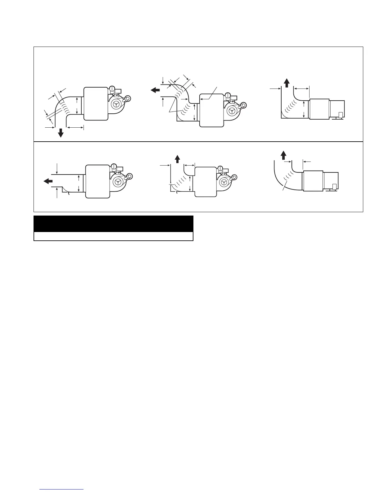
When installing the heater, always follow good duct design
practices for even distribution of the air across the heat
exchanger. Recommended layouts are shown in figure 9.1.
When installing blower units with ductwork the following must
be done.
1. Provide uniform air distribution over the heat exchanger.
Use turning vanes where required. See figure 9.1.
2. Provide removable access panels in the ductwork on the
downstream side of the unit heater. These openings should
be large enough to view smoke or reflect light inside the
casing to indicate leaks in the heat exchanger and to check
for hot spots on exchanger due to poor air distribution or
lack of sufficient air.
3.
If ductwork is connected to the rear of the unit use Modine
blower enclosure kit or if using field designed enclosure
maintain dimensions of blower enclosure as shown on page 26.
Additional Requirements for Installation of
Blower Models (BD UNITS)
Determining Blower Speed
The drive assembly and motor on all gas-fired blower unit
heaters are factory assembled. The adjustable motor sheave
has been pre-set to permit operation of this unit under average
conditions of air flow and without any external static pressure.
The motor sheave should be adjusted as required when the
unit is to be operated at other than average air flows and/or
with external static pressures. Adjustment must always be
within the performance range shown on pages 18 and 19 and
the temperature rise range shown on the unit’s rating plate.
To determine the proper blower speed and motor sheave turns
open, the conditions under which the unit is to operate must be
known. If the blower unit is to be used without duct work,
nozzles or filters, the only criteria for determining the motor
sheave turns open and blower speed is the amount of air to be
delivered. The performance tables for blower models are shown
on pages 18 and 19. As an example, a model BD 350 unit,
operating with no external static pressure, that is, no duct work,
nozzles, etc., and is to deliver an air volume of 6481 cfm (cfm =
cubic feet of air per minute) requires that the unit be supplied
with a 5 hp motor, a -207 drive, and the drive sheave must be
set at 2.5 turns open to achieve a blower speed of 960 rpm
(see performance table for units with or without blower
enclosure, page 18). See "Blower Adjustments" on page 10 for
setting of drive pulley turns open.
If a blower unit is to be used with ductwork or nozzles, etc., the
total external static pressure under which the unit is to operate,
and the required air flow must be known before the unit can be
properly adjusted. Any device added externally to the unit, and
which the air must pass through, causes a resistance to air
flow. This resistance is called pressure loss. The total of the
pressure losses must be determined before adjusting the
blower speed.
If Modine filters are used, the expected pressure loss through
the filters is included in the performance data on page 19. If
Modine supplied discharge nozzles are used, the expected
pressure drop of the nozzles can be found footnoted at the
bottom of page 22. If filters, nozzles or ductwork are to be used
with the unit, and they are not supplied by Modine, the design
engineer or installing contractor must determine the pressure
loss for the externally added devices or ductwork to arrive at
the total external static pressure under which the unit is to
operate.
Once the total static pressure and the required air flow are
known, the operating speed of the blower can be determined
and the correct motor sheave adjustments made. As an
example, let's say, a model BD 350 is to be used with a Modine
supplied blower enclosure and Modine supplied filters attached
to someone else's ductwork. The unit is to move 6481 cfm or
air flow against an external static pressure of 0.2" W.C. Also,
0.2" W.C. must be added for the filter pressure drop for a total
of 0.4" W.C. total pressure drop. Entering the performance table
on page 18 for a BD 350, at 6481 cfm and 0.4" W.C. static
pressure, it is seen that the unit will require a 5 hp motor using
a -207 drive, and the motor sheave should be set at .5 turns
open to achieve a blower speed of 1050 rpm. You can see this
example differs from similar conditions in paragraph 2 by the
number of turns open and a higher rpm, which is needed to
overcome the added external static pressure from the filters.
9
INSTALLATION
MIN.
12" MIN.
3" MAX.
3" MIN.
3" MIN.
MIN.
3" MAX.
MIN.
MIN.