15
➀
➁
➂
➃
➄
➅
➆
➇
➈
All units include the standard (STD) features. The unit must be
reviewed to determine the optional (OPT) features that may have
been supplied with the unit.
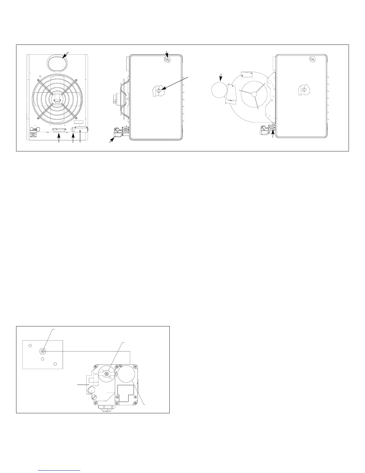
(1) Gas Valve
a) Single Stage Gas Valve - (STD)
The main gas valve is factory installed on the unit heater gas train.
The main gas valve provides the pilot, regulator, main gas, and
manual shutoff functions. For additional information, see the
supplier literature included with the unit.
b) Two Stage Gas Valve - (OPT)
The two-stage gas valve is factory installed on the unit heater gas train.
The two stage gas valve provides the pilot, regulator, main gas (100%
and 50% fire), and manual shutoff functions. For additional information,
see the supplier literature included with the unit.
c) Mechanical Modulating - (OPT)
Mechanical modulation utilizes a main gas valve as well as a
mechanical modulating gas valve (not shown). The mechanical
modulating valve includes a hydrostatic sensing bulb that is
temporarily affixed to the side of gas train to be field installed in
ductwork. The discharge air temperature is field set by the control
dial on the modulating gas valve. Refer to Control Operating
Sequence - Mechanical Modulating Gas Controls for set point
temperatures.
Figure 15.1
Mechanical Modulation Sensing Bulb
(2) Ignition controller - (OPT)
The ignition controller is factory installed on the back of the unit
heater with the spark igniter and sensor located on the burner.
For both natural and propane gas units, the ignition controller is
100% shut-off with continuous retry. On a call for heat, the system
will attempt to light the pilot for 70 seconds. If the pilot is not
sensed for any reason, the ignition control will wait for
approximately six minutes with the combination gas control closed
and no spark. After six minutes, the cycle will begin
again. After three cycles, some ignition controllers lockout for
approximately one hour before the cycle begins again. This will
continue indefinitely until the pilot flame is sensed or power is
interrupted to the system.
(3) Time Delay Relay - (STD on all but Mech. Mod.)
The time delay relay is factory installed in electrical junction box.
The time delay relay allows the gas controls to operate for
approximately 30 to 90 seconds before the blower starts. This
allows the heat exchanger a warm up period so that the initial
delivered air is not cool. The time delay relay also keeps the motor
running for approximately 30 - 90 seconds after the call for heat
has been satisfied to remove the residual heat from the heat
exchanger. For single-phase units below 2 Hp, the time delay relay
controls the motor directly. For single-phase units 2 Hp and greater
and all three phase units, the time delay relay controls the motor
starter.
Note: Mechanical modulation units are used on make-up air only
and do not require time delay relays. Therefore, mechanical
modulation units are not supplied with time delay relays.
(4) Low Voltage Terminal Board - (STD)
The low voltage terminal board is located in electrical junction box.
The terminal board is labeled to match the electrical wiring
diagram provided with the unit. All low voltage field wiring
connections should be made to the exposed side of the terminal
board (exterior of electrical junction box) to prevent miswiring by
modifying the factory wiring which is inside the electrical junction
box.