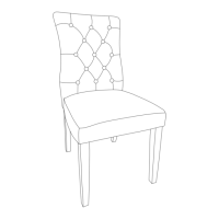
Do you have a question about the modway EEI-3875-WHI and is the answer not in the manual?
| Product Type | Accent Chair |
|---|---|
| Color | White |
| Frame Material | Wood |
| Armrest Height from Seat | 7" H |
| Style | Modern |
| Assembly Required | Yes |
| Backrest Dimensions | 16" H |
| Product Name | EEI-3875-WHI |
Identifies the Dowel/Wood hardware piece (A) for assembly.
Identifies the Cambolt/Metal hardware piece (B) for assembly.
Identifies the Camlock/Metal hardware piece (C) for assembly.
Identifies the Knob/Metal hardware piece (D) for assembly.
Identifies the Screw/Metal hardware piece (E) for assembly.
Identifies the Screw/Metal hardware piece (F) for assembly.
Identifies the Hinges/Metal hardware piece (G) for assembly.
Identifies the Shelf pin/Metal hardware piece (H) for assembly.
Identifies the Screw/Metal hardware piece (I) for assembly.
Identifies the Bracket/Metal hardware piece (J) for assembly.
Identifies the Screw/Metal hardware piece (K) for assembly.
Identifies the Stopper/Plastic hardware piece (L) for assembly.
Identifies the Screw/Metal hardware piece (M) for assembly.
Identifies the Screw/Metal hardware piece (N) for assembly.
Identifies the Side Panel Left component (1).
Identifies the Side Panel Right component (2).
Identifies the Bottom Panel component (3).
Identifies the Base Panel 1 component (4).
Identifies the Back Panel 1 component (5).
Identifies the Adjustable Shelf component (6).
Identifies the Front Panel component (7).
Identifies the Base Panel 2 component (8).
Identifies the Door Left component (9).
Identifies the Door Right component (10).
Identifies the Vertical Panel 1 component (11).
Identifies the Vertical Panel 2 component (12).
Identifies the Vertical Panel 3 component (13).
Identifies the Vertical Panel 4 component (14).
Identifies the Base Panel 3 component (15).
Identifies the Back Panel 2 component (16).
Carefully insert Wood Dowels (A) into designated holes on relevant parts.
Use a Philips screwdriver to insert Cambolt (B) into pre-drilled holes.
Secure the Door Stopper (L) to the Bottom Panel (3) using Screw (K).
Assemble Shelf Panel by securing Base Panel (15) to Adjustable Shelf (6) with Screws (I).
Attach Door Hinges (G) to Doors (9, 10) using Screws (F).
Assemble Front Frame by securing Panels (7, 8) to Vertical Panels (11, 12) using Camlocks (C) and Cambolts (B).
Assemble Back Frame by securing Back Panels (5, 16) to Vertical Panels (14, 13) using Camlocks (C) and Cambolts (B).
Attach Bottom Panel (3) and Base Panel (4) to Side Panel Left (1) using Camlocks (C) and Cambolts (B).
Attach Side Panel Right (2) to Base Panel (4) and Bottom Panel (3) using Camlocks (C) and Cambolts (B).
Combine Carcass Assembly with Back Frame Assembly using dowels and Cambolts (B), securing with Camlocks (C).
Attach Front Frame Assembly to the Semi Completed Vanity structure using dowels and Cambolts (B), securing with Camlocks (C).
Insert Shelf Pins (H) into pre-drilled holes to support the adjustable shelf.
Align and secure the Shelf Panel Assembly to the shelf pins.
Adjust door hinges for alignment using provided screws.
Attach Door Knobs (D) to Doors (9, 10) using Screws (E).
Secure Knobs (D) to the Front Panel (7) using Screws (E).
Secure Metal Brackets (J) to the top corners of the vanity using Screws (F).
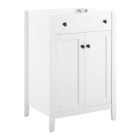
Prepare for wall mounting; note that screws and plugs are not provided.
Indicates that the vanity assembly process is finished.
Apply silicone compound around the vanity base and carefully place the vanity top.