EasyManua.ls Logo

modway EEI-3439 User Manual

modway EEI-3439
15 pages
To Next Page IconTo Next Page
Page #1 background imageLoading...
Page #1 background image
Customer Service 908-368-1025www.modway.com Page 1 of 14
Thank you for purchasing the MODWAY TV STAND !
Before you start, here are some helpful advice:
1.We suggest you spend a short time reading through this leaflet and then follow the simple step-by-step
instructions.
2. it is assembled by two adults, on a carpeted or
padded area, in the room that it is intended for. Approximate assembly time: 60 minutes.
3.Please do not use any tools other than those provided or recommended in these instructions.
4.Please do not throw away any of the packaging or instructions until you have checked all the components and
hardware and the furniture is fully assembled.
5.Assemble all components loosely until advised to tighten. Depending on use, it may be necessary to tighten the
components from time to time, so please save the tools that have
been provided.
6.Please keep all pieces out of reach of children.
EEI-3439
A) Cambolt/Metal
Screw/Metal
Screw/Metal Screw/Metal U Support /MetalWedge/Plastic
Screw/Metal Screw/MetalKey/Metal
CamLock Big/Metal
Dowel Big/Wood
Dowel Small/Wood
CamLock Small/Metal
Rell/Metal
Ø 6 x 35 mm
x 25
F)
x 16
B)
Ø 15 mm
x13
C)
x
12
D)
x
32
E)
x
20
K)
x 46
G)
x 1
H)
x 6
I)
x 36
J)
x 24
L)
x 10
N)M)
x 10
Hardware :
Ø 12 mm Ø 8 x 30 mm Ø 6 x 30 mm
L 4
M 6.5 x 10.5 mm
M 3.5 x 13 mm M 8 x 39 mmM 7 x 50 mm
x 1
O)
300 mm
TV Stand
M 3.5 x 15.5 mm
9 x 14 x 10 mm
1500 x 20 x 20 mm
Owing to the size and weight of the TV Stand, we recommend that
x 1
Screwdriver (Not Include)

Other manuals for modway EEI-3439

Question and Answer IconNeed help?

Do you have a question about the modway EEI-3439 and is the answer not in the manual?

modway EEI-3439 Specifications

General IconGeneral
CategoryIndoor Furnishing
Assembly RequiredYes
StyleModern
Product TypeChair
Frame MaterialWood
Armrest Height25.5"H
Upholstery MaterialFabric
Leg MaterialWood

Summary

Hardware Components

Hardware A: Cambolt/Metal

Metal cambolt used for initial assembly stages.

Hardware B: CamLock Big/Metal

Large metal cam lock for securing larger components.

Hardware C: CamLock Small/Metal

Small metal cam lock for smaller part connections.

Hardware D: Dowel Big/Wood

Large wooden dowel for structural support and alignment.

Hardware E: Dowel Small/Wood

Small wooden dowel for precise alignment of parts.

Hardware F: Screw/Metal (M7 x 50 mm)

Long metal screw for robust fastening of major components.

Hardware G: Key/Metal

Metal key used in conjunction with cam locks.

Hardware H: Rell/Metal

Metal component, likely a bracket or support.

Hardware I: Screw/Metal (M3.5 x 13 mm)

Medium-sized metal screw for general assembly.

Hardware J: Screw/Metal (M6.5 x 10.5 mm)

Shorter, wider metal screw for specific connections.

Hardware K: Screw/Metal (M3.5 x 15.5 mm)

Longer medium-sized metal screw for varied assembly.

Hardware L: Wedge/Plastic

Plastic wedge for stabilizing or securing parts.

Hardware M: Screw/Metal (M8 x 39 mm)

Very long metal screw for substantial structural connections.

Hardware N: U Support/Metal

U-shaped metal support for reinforcing joints.

Hardware O: Screwdriver (Not Included)

Essential tool for driving screws, not provided.

Assembly Instructions

Step 1: Initial Setup

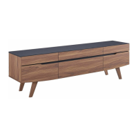
Preparation and attachment of base components to the top board.

Step 2: Side Panel Attachment

Connecting side panels to the central structure.

Step 3: Back Panel Integration

Attaching the back panel to the assembled sides.

Step 4: Attaching Vertical Supports

Connecting vertical support elements to the main frame.

Step 5: Securing Top Panel

Fastening the top panel to the assembled structure.

Step 6: Leg Preparation

Assembling leg components with base boards.

Step 7: Leg Attachment

Connecting the assembled legs to the main unit.

Step 8: Underside Support

Attaching support elements to the underside of the stand.

Step 9: Drawer Slide Installation

Mounting drawer slides onto the internal frame.

Step 10: Internal Dividers

Installing internal shelf or divider panels.

Step 11: Base Board Attachment

Securing base boards for drawers or shelves.

Step 12: Drawer Fronts

Attaching drawer fronts to the drawer boxes.

Step 13: Drawer Box Assembly

Connecting drawer box components.

Step 14: Drawer Sides

Attaching drawer sides to the drawer front and back.

Step 15: Drawer Base

Securing the base panel to the drawer structure.

Step 16: Final Drawer Check

Reviewing the assembled drawers.

Step 17: Drawer Internal Parts

Attaching internal components to drawer slides.

Step 18: Drawer Installation

Inserting assembled drawers into the main unit.

Step 19: Drawer Unit Assembly

Assembling drawer units for installation.

Step 20: Drawer Runners

Attaching drawer runners to the drawer boxes.

Step 21: Drawer Insertion

Sliding completed drawers into the TV stand.

Step 22: Handle Attachment

Mounting handles onto the drawer fronts.

Step 23: Final Assembly Complete

Confirmation that the TV stand assembly is finished.
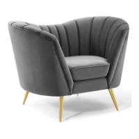
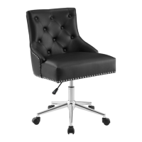
Related product manuals