10 Chapter 3. Operation
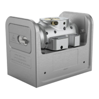
Spring plunger
λ
adjust Filter notch
Spindle-clamp lock screw
Filter assembly (clamp)
Filter assembly (spindle)
Figure 3.1: Filterangleadjustment, showingtheprimary wavelengthadjustment
screwandcounter-actingspringplunger. Mechanicalversionfrom2023shown
(serial A323xxxxx and above).
Afterthetargetwavelengthhasbeenachieved,SPAN canbeadjustedto
increasethewidthofthepiezoscan.AdjustmentsoftheSPANknobshould
be gradual, and careful adjustments of the diode current may berequired
inorderto maintainsingle-modeoperation. Confirmthatyour laseris
capableofreachingthemode-hopfreescanrange(MHFR)specifiedin
the lasertest report.If the MHFRis less than specified, proceedto §3.3
and 4.1.
3.3 Mode-hops
Mode-hops area frequent occurrencewith externalcavity diodelasers.A
mode-hopisadiscontinuitywhentuningorscanningthelaserwavelength.