14 Chapter 3. Operation
TheextendedchassisversionofaMOGLabslaserallowsinternalmounting
ofaFaradayisolator(seefigure3.6). Alignmentisstraightforward: the
isolatorshouldbeconcentricwiththelaserbeam,androtatedaxiallyso
thatthe firstpolariser isparalleltothe polarisationof theinput laser
beam. Dependingon wavelength,thetransmission varies fromabout70%
to 98%, with 90 to 95% typical at 780nm.
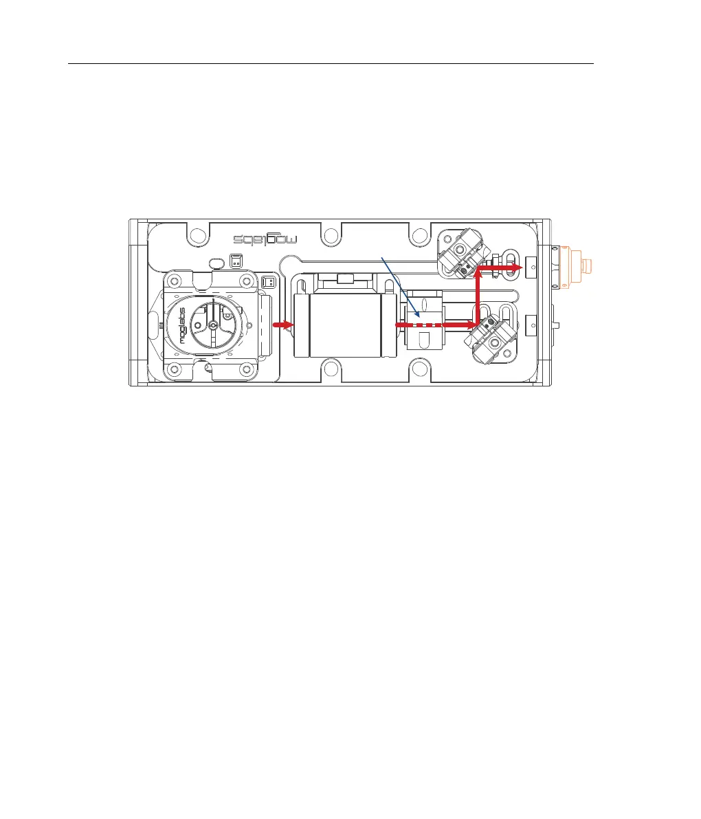
M1
M2
Faraday
isolator
Fibre
coupler
Cylindrical
telescope
Figure 3.6: SchematicoftheextendedchassislasershowingFaradayisolator,
and two mirrors used for aligning the beam to a single-mode fibre.
Theisolatortypicallyhasahalf-waveretardationwaveplateontheoutput,
forcontrollingtheangleofpolarisationofthebeam. Thewaveplateis
typicallymountedinsidetheend-capoftheisolator(seefigure3.7)or
alternatively in a freestanding rotation mount fixed to the chassis.
Thewaveplate anglein theplane orthogonaltotheopticalaxis mayneed
adjustment, for example to vary the power ratio for the two beams exiting
aPBS, toalignthepolarisationto amoreconvenient horizontalorvertical
axisforexperiments,ortoaligntoapolarisationpreservingfibre.Toadjust
thewaveplateangle,loosentheradialsetscrewholdingthewaveplate,
rotate, and restore set screw tension. Some isolators use a 0.035” or
0.9mm hex key while others require a 1.5mm hex key (see figure 3.7).
On lasers withfibre-coupled output,a second waveplatemay bemounted
directlybeforetheexitfaceofthelaser. Thewaveplateallowsseparate
polarisation control for the beam reflected from M1 to match the fibre
polarisation axis.