4.3 Threshold optimisation 23
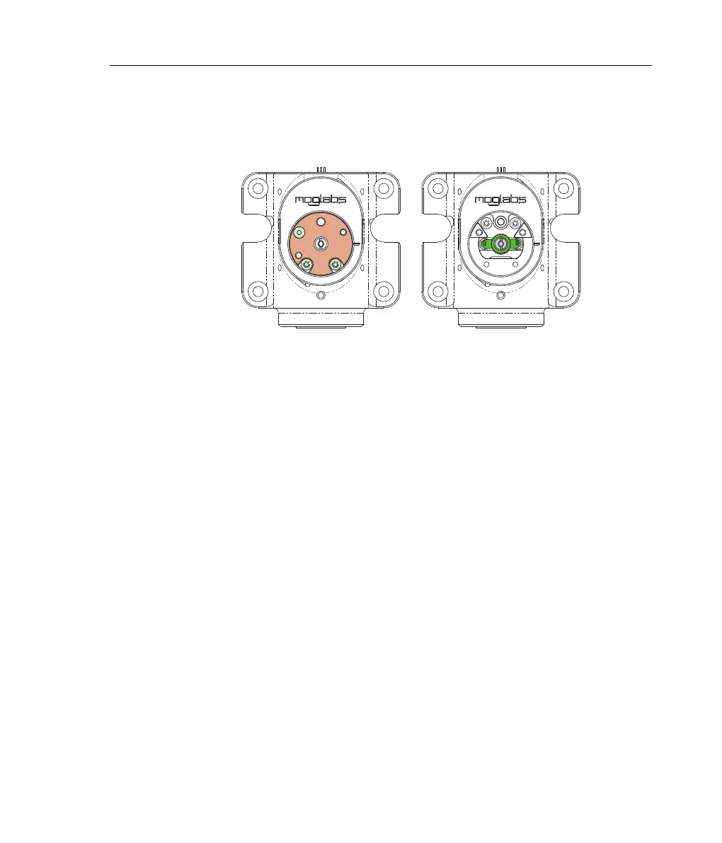
4. Removethebrassclampfromthecentralspindle,thenremovethe
threehexdrivescrewsholdingthecircularplateontopofthespindle
(see figure 4.2).
Figure 4.2: Removingtheintracavityfilterassembly. a)Threescrewsholdthe
top plate (pink)over the spindle.b) Spindle (green) must be alignedas pictured
before removal.
5. Rotatethefilterspindlesuchthatthefilteralignmentmark(themark
on the spindle, not the mark on the brass clamp) is aligned parallel
with the optical axis.
6. Gentlyprisethefilterassemblyfromthelaserbarrel(seefigure4.2).
If the filter seems stuck, it may be caught on the cateye output
couplerorlaserdiodetubesormayberotatedfromtherequired
orientation (see previous step).
7. Turnthe DLCon andadjustCURRENTto 5–10mAabovethethresh-
old specifiedin thelaser testreport.You shouldhave atleast 1mW
ofoutputpower,otherwiseincreasethecurrentfurther,butdonot
exceed the maximum safe current specified in the laser test report.
8. Monitor the laseroutput powerusing a powermeter asclose tothe
cateyeassemblyaspossible,thatis, beforetheisolator,withthe
powersensorangledslightlyfromorthogonaltotheopticalaxisto
protect the laser from back reflections from the sensor surface.
9. Adjust the cateye lens focus by rotating the threaded lens mount of