BUILD. MODIFY. REPAIR.
14
500 K 25 K 250 K 500 K 500 K
1 M
500 K
PREAMP TUBE
9 PIN SOCKET
12AX7
PREAMP TUBE
9 PIN SOCKET
12AX7
PHASE INVERTER
9 PIN SOCKET
12AX7
POWER TUBE
9 PIN SOCKETS
EL84
RECTIFIER TUBE
9 PIN SOCKET
EL84
CAN CAPACITOR
32µF + 32µF
@500V
BRITISH STYLE 18watt
POWER TRANSFORMER
FUSE HOLDER
A/C POWER JACK
INDICATOR LIGHT
MAINS SWITCH STANDBY SWITCH
GAINTREBEL
MASTER
VOLUMETONEMIDDLE
BASS
IMPEDANCE SELECTOR
J1 SPEAKER JACK
J1 INPUT JACK
J1 INPUT JACK
J2 INPUT JACK
J2 SPEAKER JACK
10 nF
10 nF
10 nF
10 nF
4.7 nF
22 nF
22 nF
22 nF
100K
100K
100K
100K
820 Ω
820 Ω
10K
47K
47K
470K
470K
470K
470K
470K
470K
470K
5.1K
16uF
22 nF
22 nF
680 nF
47 pF
500 pF
500 pF
25 uF
+
100 Ω
100 Ω
2.7 K
2.7 K
5.1K
820 Ω
100K
100K
2.7 K
68K
100K
10 K
10 K
1M
130 Ω
25 uF
+
British Style 18watt TMB
Revision 3.0
04/21/2019
CAN CAPACITOR
32µF + 32µF
@500V
68K
1M
68K
FROM INDICATOR LAMP
FROM MAINS SWITCH
FROM POWER TRANSFORMER
FROM OUTPUT TRANSFORMER
SPEAKER WIRE HARNESS ASSEMBLY
TO GROUND TAB TO GROUND TAB
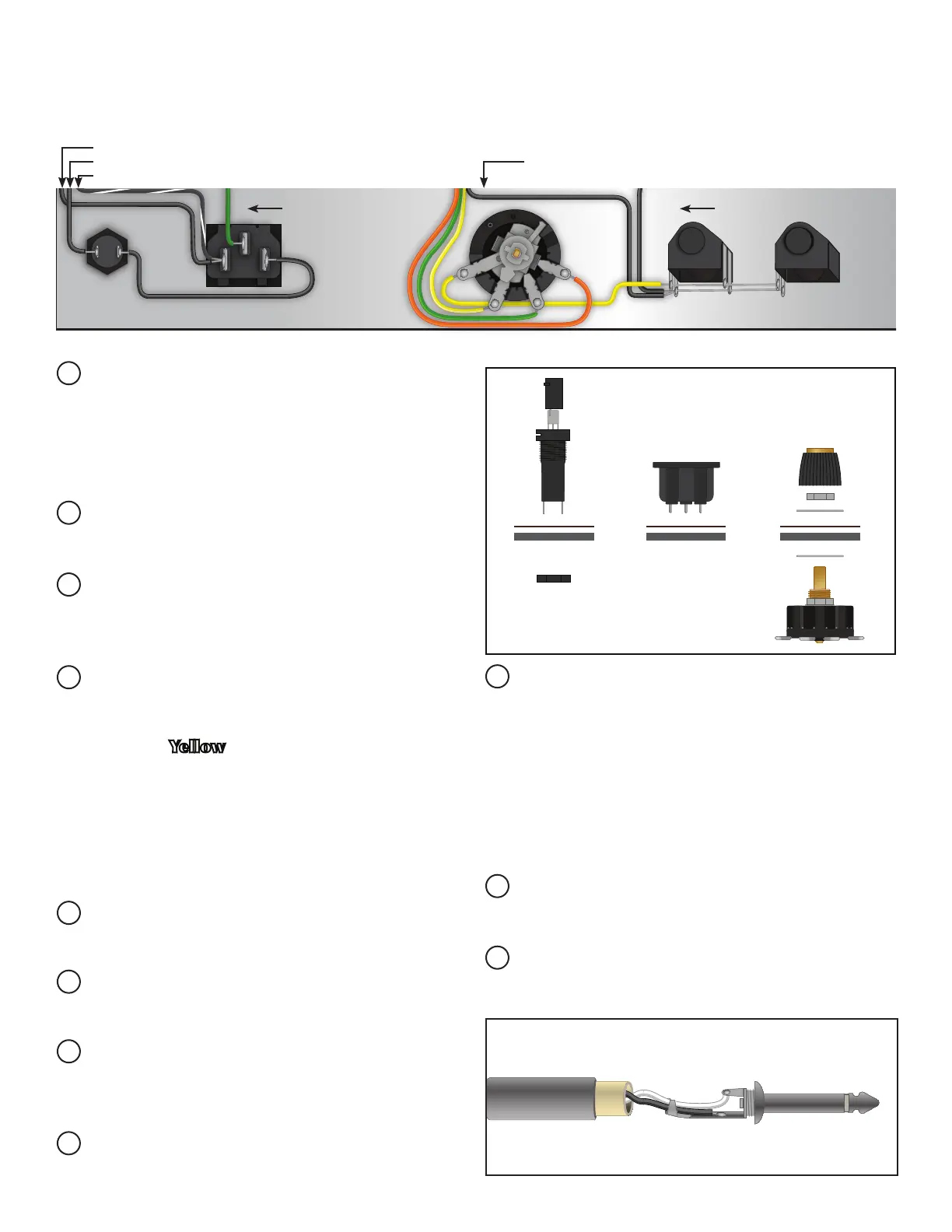
Install rear faceplate, fuse holder, impedance se-
lector and speaker jacks on the back of the chassis
using included hardware. Make sure the impedance
selector is snug so that it does not rotate when you
are switching between different output impedances.
Snap in A/C Power Jack into chassis with the center
pin oriented closest to the inside of the chassis.
Follow the wiring diagram and begin with wiring
the fuse holder and working to the right towards
the speaker jacks.
Install the knob on the impedance selector, Note which
color wire that the selector tab is pointing to, and align
the knob to that number on the back panel, tighten the
set screw. (Yellow 4 Ω, Green 8 Ω, Orange 16 Ω).
Twist the two 15” lengths of black and white 18
gauge stranded wire together.
Push the insulation back about 1⁄2” from both wires
on one end and tin them.
Unscrew the cover off of the 1⁄4” plug. Solder the
white wire to the tip terminal. Solder the black wire
to the sleeve as shown in the illustration.
Bend the two retaining tabs over to hold the wires
to the jack.
Install the clear plastic shielding over the wiring,
then install the cover on the jack.
On the other end of the wiring harness, push back
the insulation on the wires by 1⁄2”, twist and tin them.
Use a small at head screw driver to remove the
fuse holder cap. Install the fuse into the cap and
reinstall into the fuse holder, push in and twist to
the right about a quarter turn.
SECTION 10:
REAR PANEL COMPONENT INSTALLATION AND WIRING
SECTION 11:
SPEAKER WIRING & INSTALLATION (For Combo Amp only)
ECC83S ECC83SECC83S
ONBASSMIDDLETREBLEGAINTONEVOLUME
MASTERINPUTS
STANDBY
ON
MAINS
INDICATOR
EL 84EL 84
EZ 81
ECC83S ECC83SECC83S
EL 84EL 84
EZ 81
MAINS FUSE
MAINS INPUT
IMPEDANCE
4 8
16
SPEAKERS
SPEAKER WIRE HARNESS ASSEMBLY:
FUSE HOLDER
& FUSE
A/C POWER
JACK
IMPEDANCE
SELECTOR
SWITCH