BUILD. MODIFY. REPAIR.
8
2.7 K
68K
10 K
1M
500 K 25 K 250 K 500 K 500 K
1 M
500 K
1M
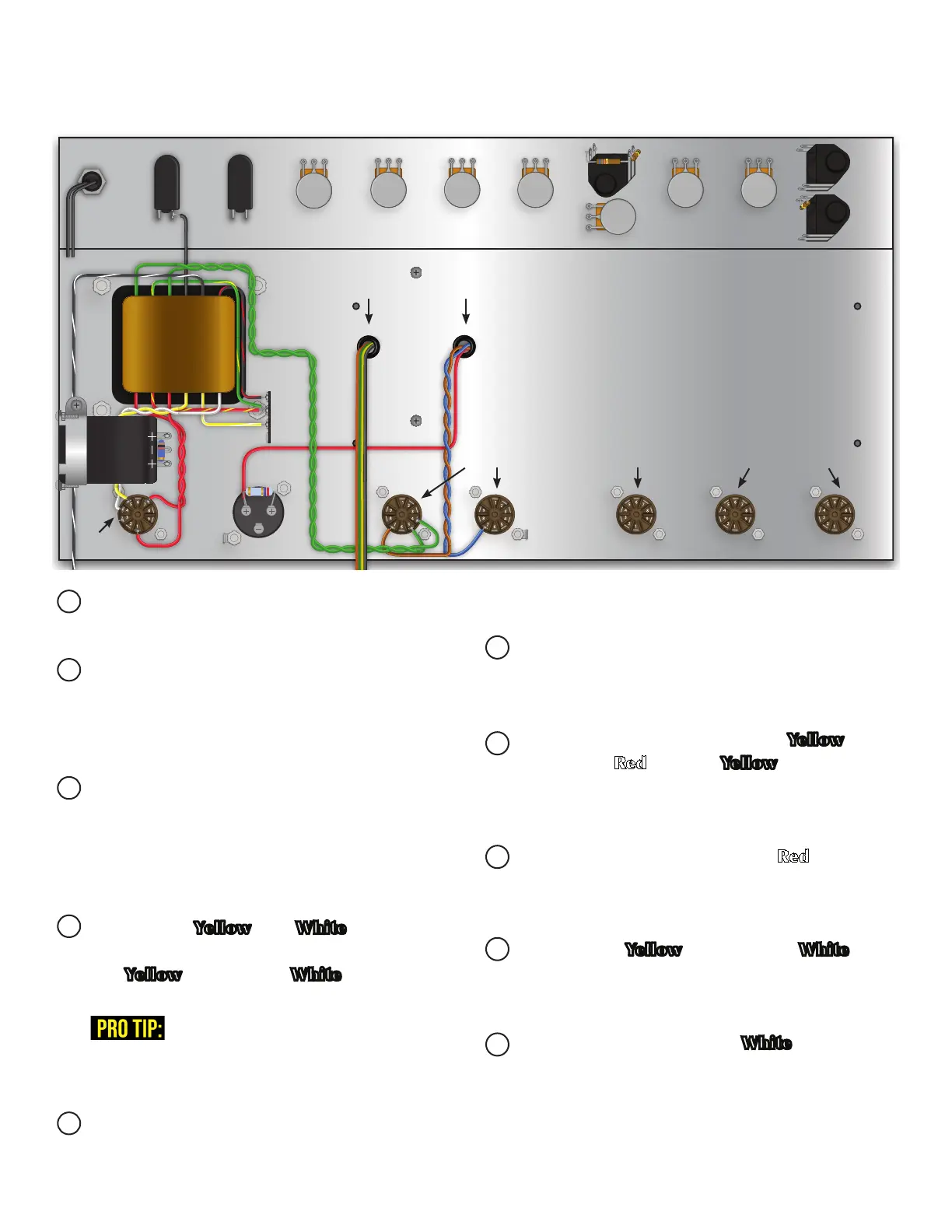
SECTION 6:
TRANSFORMER WIRING
Twist all matching pairs of wires coming out of the
power transformer.
Measure length needed for each wire, allow your-
self extra lead and cut to length. This will eliminate
excess wire and free up space in your chassis. Apply
this principle to all leads.
Prepare the two Red wires from the power trans-
former (HV secondary). Connect one wire to pin 1
and the other to pin 7 of the rectier tube socket.
NOTE: These wires carry AC voltage, so either
wire can go to either pin 1 or 7.
Prepare the Yellow and White wires from the
power transformer (5v rectier lament). Connect
the Yellow to pin 5 and White to pin 4 of the
rectier tube socket.
PRO Tip: On stranded wire, twist the stranded end
tight before tinning. This will make it easier to put
through the lug.
Prepare the two Green wires from the power
transformer (6.3v tube filament) and connect
them to the 5 and 4 pins on the power tube
socket closest to the power transformer.
Prepare the Black wire and connect to the mains
switch on the lug furthest from the power trans-
former.
Prepare the Green wire with the Yellow stripe.
Prepare the Red with the Yellow stripe and con-
nect both wires to the grounded lug on the terminal
strip.
Prepare the Black wire with the Red stripe and
connect it to an empty, non-grounded lug on the
terminal strip.
Prepare the Yellow wire with the White stripe
and connect it to an empty, non-grounded lug on
the terminal strip.
Run the Black wire with the White stripe toward
the back panel of the chassis where the power plug
will be installed.
FROM OUTPUT TRANS.
POWER
TUBE SOCKETS
EL84/6BQ5
PHASE INVERTER
TUBE SOCKET
ECC83/12AX7
PREAMP
TUBE SOCKETS
ECC83/12AX7
RECTIFIER
TUBE SOCKET
EZ81