www.mojotone.com
15
SECTION 12:
INITIAL CHASSIS TESTING
Starting from the left side of the chassis, ensure
all solder joints and connections are good. Physically
inspect every tube socket closely, making sure there
are not any extra wires touching other pins.
Look and listen for loose hardware by shaking chassis.
Ensure chassis is free from debris before plugging
in. Check for pinched or burnt wire insulation.
Adjust lead dress so it is easy to see components.
Power on amp without the tubes installed.
Using a multimeter set to AC voltage, check the
power transformer secondary AC voltages (at tube
socket for laments). This will be pins 4 and 5 and pin
9 on the preamp tubes and pins 4 and 5 on the EL84’s.
Turn off the amp and install the EZ81/6CA4 rectier tube.
Turn on amp, do NOT turn on the Standby switch yet, and
allow it to warm up (approximately one minute). Watch
for any kind of arcing or smoke from any component
or transformer. If you see anything, shut down the amp
immediately. Disconnect the amplier from wall socket,
check voltages on the lter capacitors (DC voltage), make
sure they are drained, and then recheck your wiring.
Check the B+ voltages on pin 3 on the rectier socket.
Turn the Standby Switch to ON. Watch for any kind of
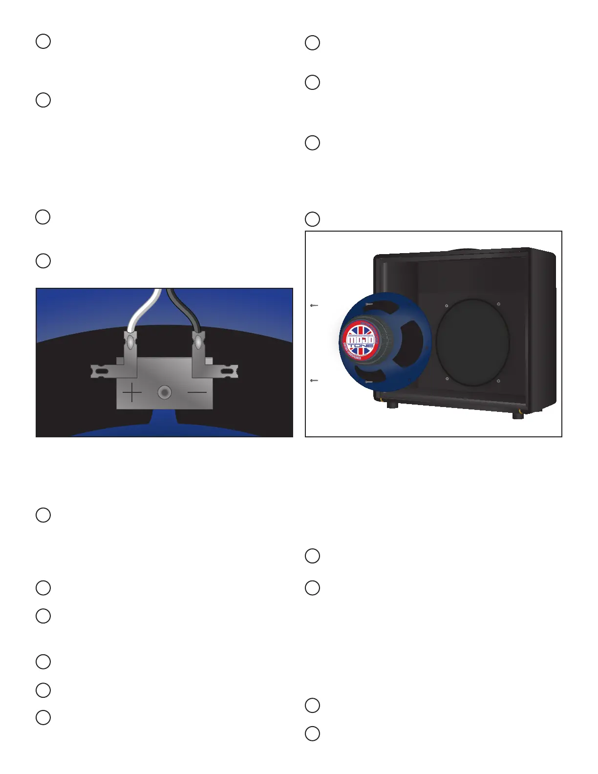
With a pair of needle nose pliers, take the tinned
wire and make a small “hook” on both the white &
black wires.
Insert the white wire “hook” into the positive (+)
terminal on the back of the speaker. Use the nee-
dle nose pliers to carefully crimp the “hook” on the
terminal, forming a mechanical connection. Then
solder the wire to the terminal. Repeat the same pro-
cess with the black wire on the negative (-) terminal.
Remove the upper and lower back panel of the
cabinet.
Mounting holes for the chassis have already been
drilled on the upper back panel.
Remove the four mounting screws from the speak-
er bafe.
With the cabinet laying face down, place the
speaker on the bafe, line up the speaker mounting
holes with the holes on the bafe.
Finger tighten the mounting speaker screws. Start-
ing with the top left screw, tighten with a screw-
driver, then tighten the screw diagonally from it.
Then tighten the remaining screws in the same way.
Reinstall the lower back panel.
ECC83S ECC83SECC83S
ONBASSMIDDLETREBLEGAINTONEVOLUME
MASTERINPUTS
STANDBY
ON
MAINS
INDICATOR
EL 84EL 84
EZ 81
ECC83S ECC83SECC83S
EL 84EL 84
EZ 81
MAINS FUSE
MAINS INPUT
IMPEDANCE
4 8
16
SPEAKERS
ECC83S ECC83SECC83S
ONBASSMIDDLETREBLEGAINTONEVOLUME
MASTERINPUTS
STANDBY
ON
MAINS
INDICATOR
EL 84EL 84
EZ 81
ECC83S ECC83SECC83S
EL 84EL 84
EZ 81
MAINS FUSE
MAINS INPUT
IMPEDANCE
4 8
16
SPEAKERS
SPEAKER INSTALLATION: