BUILD. MODIFY. REPAIR.
10
SECTION 8:
BOARD ASSEMBLY & INSTALLATION
SECTION 7:
Component wiring
SAFETY FIRST! BE SURE TO TAKE NOTE OF POLARIZED CAPACITOR ORIENTATIO N FOR THE 16 UF CAP, AND (2) 2 5UF CAPS.
Begin by applying traces (or “jumper wires”) to
the board.
PRO Tip: Utilize the different sections on the post
of the turret when attaching your wires and compo-
nents. This makes for easier soldering and repair.
Once jumper wires are in place, follow wiring diagram
to create leads where necessary. These will be the wires
that go out from the component board to other compo-
nents in the circuit. Insert these leads down through the
front of the board and bend around back to secure.
PRO Tip: Use the included Wiring Diagram to
approximate lead lengths.
Starting at one end of the front side of the board,
identify the necessary components for each turret
connection and begin placing the leads into the
hole on top of the turret.
Connect The 10k metal oxide resistor between the
Positive (+) terminals on the can capacitor mounted
from the inside, and the 2.7k metal oxide resistor be-
tween the positive (+) terminals on the can capacitor
mounted from the outside.
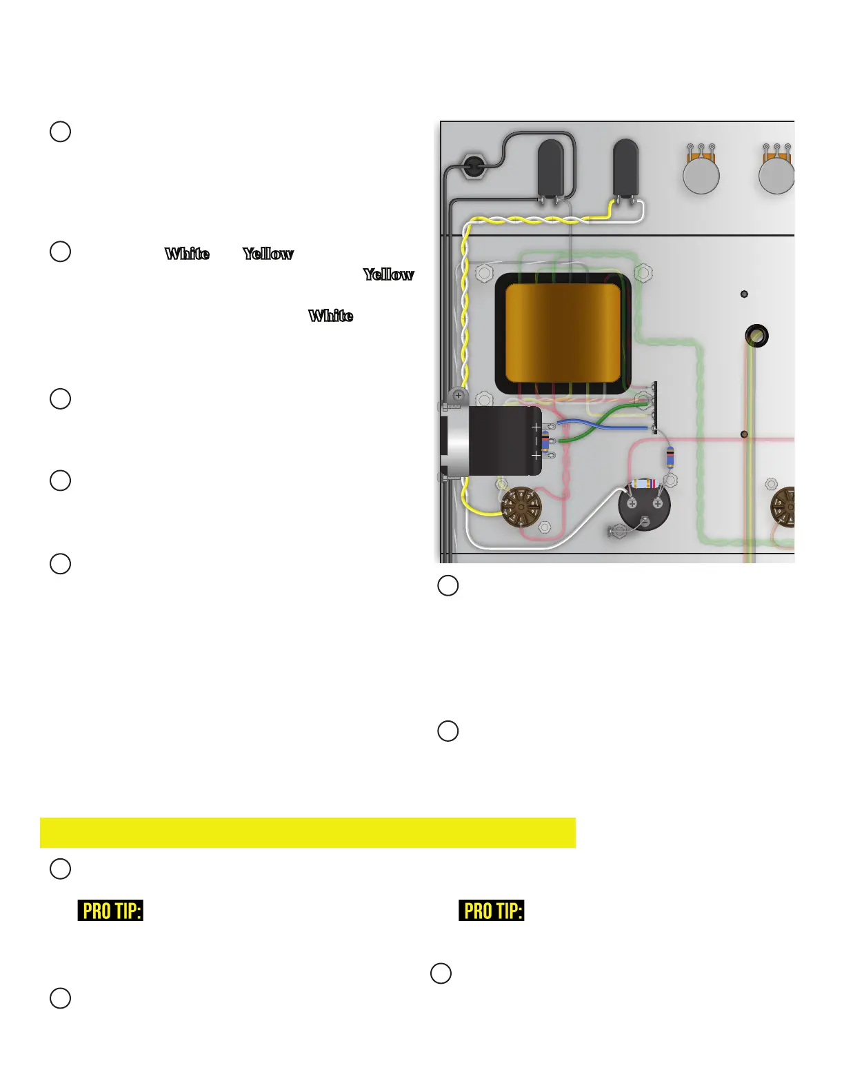
Prepare the White and Yellow wire and twist to-
gether for the standby switch. Connect the Yellow
wire from the LEFT terminal of the switch to the
3 pin on the rectier tube socket. White from the
right terminal to the LEFT (+) terminal on the can
capacitor mounted from the outside of the chassis.
Prepare the Black wire for the mains switch. Con-
nect to the left terminal of the switch and run it to
where the fuse holder will be installed.
Connect one wire from the indicator lamp to the
RIGHT terminal on the mains switch. Run the other
wire to where the power plug will be installed.
Prepare the Blue and Green wire for the can capac-
itor mounted from the inside of the chassis. Connect
the Blue wire from the RIGHT positive (+) terminal
to an open, non-grounded, lug on the terminal strip.
Connect the Green wire from the Bottom negative (-)
terminal to the grounded lug on the terminal strip.
Prepare bare wire and connect from the BOTTOM
negative (-) terminal on the can capacitor mounted
from the outside of the chassis to the closest ground
lug. Connect a 10k metal oxide resistor from the
RIGHT positive (+) terminal to the same lug the
Blue wire is connected to on the terminal strip.
Double check wiring and solder.
500 K 25 K 250 K 500 K 500 K
1 M
500 K
2.7 K
68K
10 K
10 K
1M