www.mojotone.com
17
CONGRATULATIONS!! YOU HAVE JUST BUILT YOUR VERY OWN MOJOTONE
18WATT TMB. THERE IS ONLY ONE ON THE PLANET THAT IS LIKE YOURS. WE HOPE
YOU HAVE ENJOYED THIS EXPERIENCE AND GAINED KNOWLEDGE TO HELP YOU
BECOME MORE CONFIDENT TO BUILD MANY MORE AMPS AND SPREAD YOUR
KNOWLEDGE.
SHARE YOUR BUILD WITH US WE WANT TO SEE YOUR FINISHED
AMP. SEND PHOTOS TO: SALES@MOJOTONE.COM
OR TAG US!!! @ MOJOTONE
@ MOJOTONE
SECTION 14:
SOUND TEST
SECTION 15:
TROUBLESHOOTING
DEPENDING ON THE ISSUE YOU HAVE, YOU WILL NEED TO DIAGNOSE WHICH PART
OF THE CIRCUIT IS FAULTY. TRY TO WORK THE PROBLEM ANALYTICALLY, YOU
CAN MAKE PROBLEMS WORSE OR CREATE NEW ONES BY DOING UNNECESSARY
REPAIRS. 99% OF THE TIME IT IS SIMPLE - A BAD SOLDER JOINT, NO SOLDER ON
JOINT, CAPACITOR IN BACKWARDS, ETC.
RESOURCE WEBSITES
www.ampwares.com The best resource with the most
extensive info on most vintage amps.
RESOURCE LITERATURE
Tube Guitar Amplier Essentials and All About
Vacuum Tube Guitar Ampliers by Gerald Weber
Truly must read books by Gerald Weber for any amp
tech. You can purchase these at Mojotone.
The Tube Amp Book By Aspen Pitman.
A great resource for schematics and basic tube info.
Comes with DVD that has over 800 schematics of vin-
tage tube amp technology.
RCA Tube Receiving Manual
This is one of the books that really started the guitar amp craze.
Leo Fender used this very book to develop his rst amps.
CONTACT MOJOTONE’S PRO TECHS
800-927-6656
tech @ mojotone.com
Turn on the amp and let it warm up.
After warm-up, ensure the tubes are not “red plating.”
Rotate all controls fully and listen for noise. It
is normal to have some noise at high volume levels.
Plug in an instrument cable and listen for any
crackle, pops, strange oscillations or feedback.
Leave on for a while so the tubes and compo-
nents can “burn in” - (not literally)
ROCK OUT!!
Plug the speaker into the speaker jack closest to the im-
pedance selector.
Plug in the power cord into the A/C jack on the back of
the chassis.
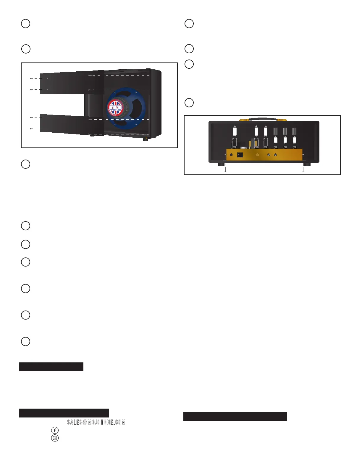
Using a screwdriver, remove the four screws holding
the back panel on the cabinet.
Carefully slide the chassis into the cabinet until the front
faceplate is ush against the front panel of the cabinet.
Carefully turn the cabinet so that it is facing down.
Locate the mounting holes on the bottom of the cabinet.
Install the four 1-1/2” 10-32 screws into the bottom of
the cabinet, through the mounting holes in the chassis.
Secure the screws with the 10-32 keps nuts.
Re-install the rear panel on the cabinet. Plug in power
cord into A/C outlet.
ECC83S ECC83SECC83S
ONBASSMIDDLETREBLEGAINTONEVOLUME
MASTERINPUTS
STANDBY
ON
MAINS
INDICATOR
EL 84EL 84
EZ 81
ECC83S ECC83SECC83S
EL 84EL 84
EZ 81
MAINS FUSE
MAINS INPUT
IMPEDANCE
4 8
16
SPEAKERS
ECC83S ECC83SECC83S
ONBASSMIDDLETREBLEGAINTONEVOLUME
MASTERINPUTS
STANDBY
ON
MAINS
INDICATOR
EL 84EL 84
EZ 81
ECC83S ECC83SECC83S
EL 84EL 84
EZ 81
MAINS FUSE
MAINS INPUT
IMPEDANCE
4 8
16
SPEAKERS
HEAD CABINET