BUILD. MODIFY. REPAIR.
6
500 K 25 K 250 K 500 K 500 K
1 M
500 K
SECTION 5:
Chassis ASSEMBLY
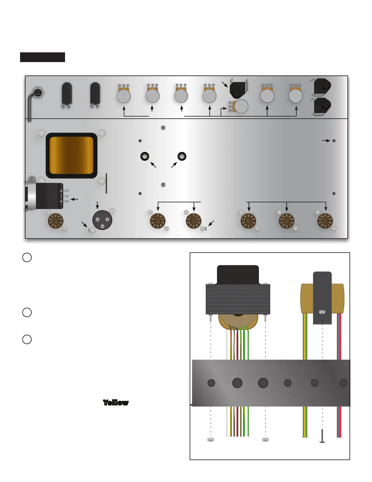
PLEASE NOTE: ALL PARTS LISTED IN THE CHASSIS PREP SECTION STARTS AT ONE END OF THE CHASSIS AND COMPLETES ON THE OPPOSITE END, BOTH TOP AND BOTTOM.
Mount the power transformer using its
pre-assembled hardware and your adjust-
able wrench. The transformer will be re-
cessed through the rectangular cutout in the
“belly” of the chassis.
Install rubber grommets in holes for output
transformer leads.
Mount the output transformer using the (2)
8-32 x 1⁄4” screws and corresponding keps
nuts onto the outside of the chassis next to
the power transformer (output transformer
is not recessed). Install the transformer so
that the Red, Blue and Brown wires go
through the grommet furthest from the pow-
er transformer. The Yellow, Black, Green
and Orange go through the grommet clos-
est to the power transformer. The screws
will go through the outside of the chassis,
and the nuts will be installed in the inside.
Use a screwdriver and adjustable wrench
to tighten.
FLATTENED VIEW OF INSIDE OF CHASSIS
INDICATOR
LAMP
MAINS SWITCH
STANDBY
POTENTIOMETERS
J1 JACK
J1 JACK
J1 JACK
9-PIN TUBE SOCKETS
9-PIN SOCKET
CAN CAPACITOR
FOR TURRET BOARD MOUNTING
4 LUG
TERMINAL
RUBBER
GROMMETS
GROUND
TAB
GROUND
TAB
POWER TRANSFORMER
OUTPUT TRANSFORMER