BUILD. MODIFY. REPAIR.
12
SECTION 9:
WIRING THE SOCKETS, JACKS & POTS
Pro Tip: This is a high gain preamp and is more
sensitive to lament hum from wiring lead dress. Take
care that signal wires are routed away from the lament
wirings and previous gain stages.
Twist tightly together a length of about 3’ of Red and
Black wire to start wiring the tube laments. Starting
with the power tube that is closest to the rectier tube,
prepare and connect the twisted wire between the tube
sockets.
PRO Tip: Make sure the power tube laments are “in
phase”. This means that the lament wires (Red and
Black twisted wire running between the power tubes
sockets) must connect to the corresponding pins be-
tween the sockets. Pin 4 to pin 4, Pin 5 to pin 5. Preamp
tubes do not have to be in phase.
When wiring the preamp tubes, Be sure to keep the
Red wires close together and centered when running
them across the tube socket to pin 5. Also note that there
is a jumper between pins 4 & 5.
PRO Tip: Since there is a wire connected to the 5 pin,
you can achieve the jumper wire to the 4 pin by strip-
ping the wire back further, running it through the 5 pin
and reach to the 4 pin. Solder the wire to both pins. Use
this method on any jumper on the tube sockets.
Follow the wiring diagram and begin wiring the tubes
sockets starting from the power tubes and work your
way across the chassis towards the preamp tubes.
Prepare two Green wires and connect one to pin
7 of the far right preamp tube and run toward the
“INPUTS” jacks. Connect the other from pin 2 and
run toward the “MASTER” jack.
Prepare the bus wire that will mount across the back of
all the pots. Start from the “BASS” control on the left side
and solder the wire on the back of each pot. This will
provide a place to run to ground since the pots are all
grounded to the chassis.
Prepare the two Black wires and connect from
the board to the ground buss wire that is installed
on the back of the pots.
Follow the wiring diagram and begin wiring the pots on the
front of the chassis. Start from the left “BASS” control and
work your way across the chassis towards the input jacks.
Prepare the Green signal wire from pin 2 of the
preamp tube and connect it to the rear left lug on
the “MASTER” input jack.
Prepare the three jumper wires and connect to the
“INPUTS” input jacks as shown.
Prepare the two Black ground wires and connect
to the “INPUTS” input jacks as shown.
Prepare the two 68K resistors and connect to the
“INPUTS” input jacks as shown. Then twist the oth-
er ends together.
Prepare the Green signal wire from pin 7 of the pre-
amp tube and connect at the junction of the two 68K
resistors. Trim the excess wire from the 68K resistors.
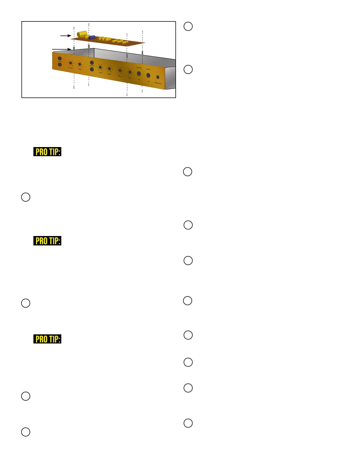
COMPLETED
TURRET BOARD
STANDOFFS
Locate the four small pre-drilled holes in the
chassis for mounting the turret board. Install
a turret board standoff on each hole using the
1/4‘‘ 4-40 screws.
Line the mounting holes on the turret board with
the turret board standoffs and secure using the
1/4‘‘ 4-40 screws.
TUBE SOCKET FILAMENT WIRING:
TUBE SOCKET WIRING:
INPUT JACK WIRING:
POTENTIOMETER WIRING: