5.2 Outputs
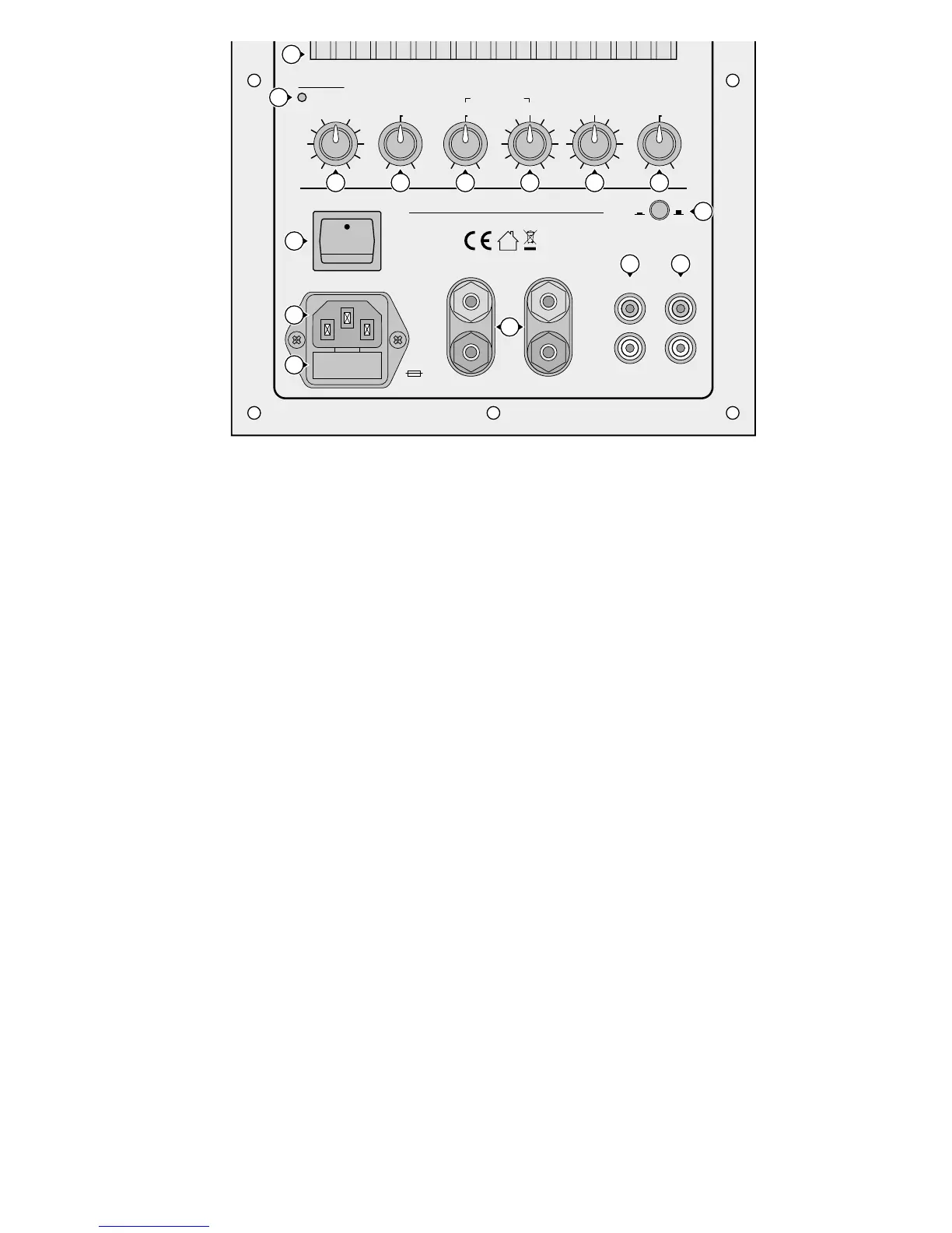
Connect the RCA jacks SAT OUT (15) to the inputs
of a stereo power amplifier operating the satellite
speakers.
In case of separable full amplifiers of high qual-
ity provided with a controlled preamplifier output
(possibly marked “Pre Out”) and a power amplifier
input (possibly marked “Amp In”), it is also possible
to insert the module SAM-2 into the full amplifier:
Connect the jacks LINE IN (14) to the preamplifier
output and the jacks SAT OUT (15) to the power
amplifier input.
5.3 Power supply
Finally connect the supplied mains cable first to
the mains jack (11) and then to a mains socket
(230 V/ 50 Hz).
6 Operation
Any adjustments and sound evaluations must only
be made in connection with the satellite speakers.
The sound should be evaluated at the final place
of hearing where a second person at the active
subwoofer should be instructed to find the best
adjustment.
1)
Switch on the active speaker system with the
switch POWER (10). As long as no input signal
is available, the system is in the power-saving
stand-by mode and the LED indicator (2) shows
red. As soon as an input signal is available, the
power amplifier is switched on and the LED
shows green.
If no signal is available, the active speaker
system will return to stand-by (LED = red) after
approx. 7minutes. If the active speaker system
is not used for a longer period, it should be
switched off with the switch POWER, otherwise
the stand-by mode will always have a low cur-
rent consumption.
If the automatic switchover between stand-
by and operation does not function optimally,
the switch-on threshold can be modified in the
range of 1 – 10 mV. The control for the switch-on
threshold is in the position RVa on the PCB of
the preamplifier (see page35
). The further the
control is turned clockwise, the higher the input
level at which the module will be switched on.
2) If a ground loop has been created by the con-
nection, humming will occur (e. g. with music
passages of low volume). This ground loop can
be interrupted with the groundlift switch (9).
On the other hand, the amplifier is not shielded
from electric noise fields if the front plate is not
grounded. In case of doubt, set the switch
alternately to find the best adjustment.
3) Use the control SUB CROSSOVER (4) to adjust
the upper crossover frequency, i. e. the fre-
quency which is not to be reproduced any more
by the subwoofer (the lower the upper cross-
over frequency, the more difficult the acoustic
localization of the subwoofer; the higher the
crossover frequency, the more powerful the bass
support). In most cases, shelf speakers and small