73
MONTEREY
BOATS
Electrical System
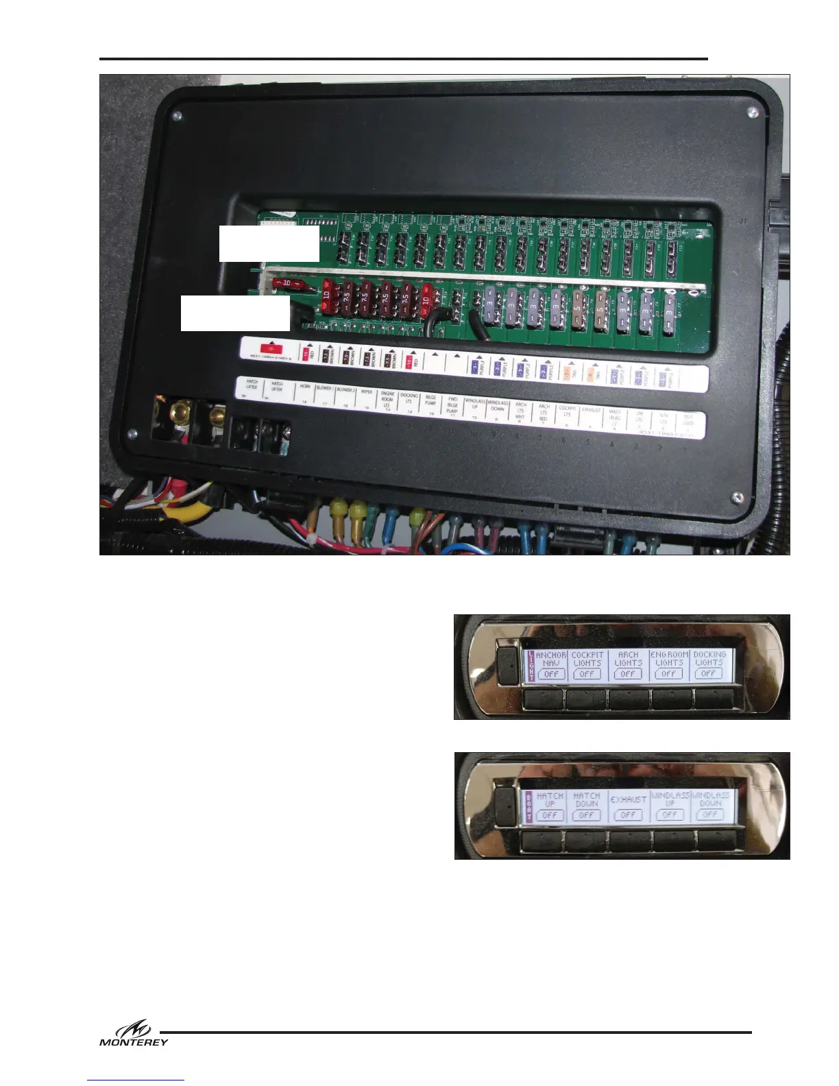
Digital Helm Switch Panels
Digital switching systems provide reduced com-
plexity and increase switching options at the
power management module, the switch harness
and the two digital switch modules at the helm.
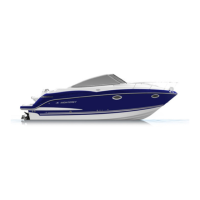
The power management module (or MUX module-
which is short for multiplexing) is located in the
compartment forward of the helm station. The
MUX module is the central brain for the system.
It is powered by the helm main breaker located
on the battery switch panel. Each circuit is pro-
tected by individual spade type fuses located in a
fuse panel built into the MUX module. The MUX
module is also where the switching of input and
output current load to the selected accessories
takes place. The controllers in the MUX module
recognize low voltage, digital signals from the
push button switches in the modules and activate
the correct combination of circuits for each switch
function (i.e. the navigation lights switch actually
forces the forward navigation lights and the anchor
light to be turned on at the same time).
Lights Page - Digital Switch Panel
Boat Page - Digital Switch Panel
Power Management Module - MUX
BYPASS
FUSE POSITION
NORMAL
FUSE POSITION
In the unlikely event of a switch failure, the fuse
can be moved into the bypass position. Simply
remove the fuse from the lower (normal) fuse
holder and place it into the upper (bypass) holder.
 Loading...