74
MONTEREY
BOATS
Electrical System
The corresponding circuit will now be “ON” for as
long as the fuse is in that position and no longer
be controlled from the switch module. When the
problem is corrected, move the fuse back to the
original position for normal operation.
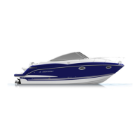
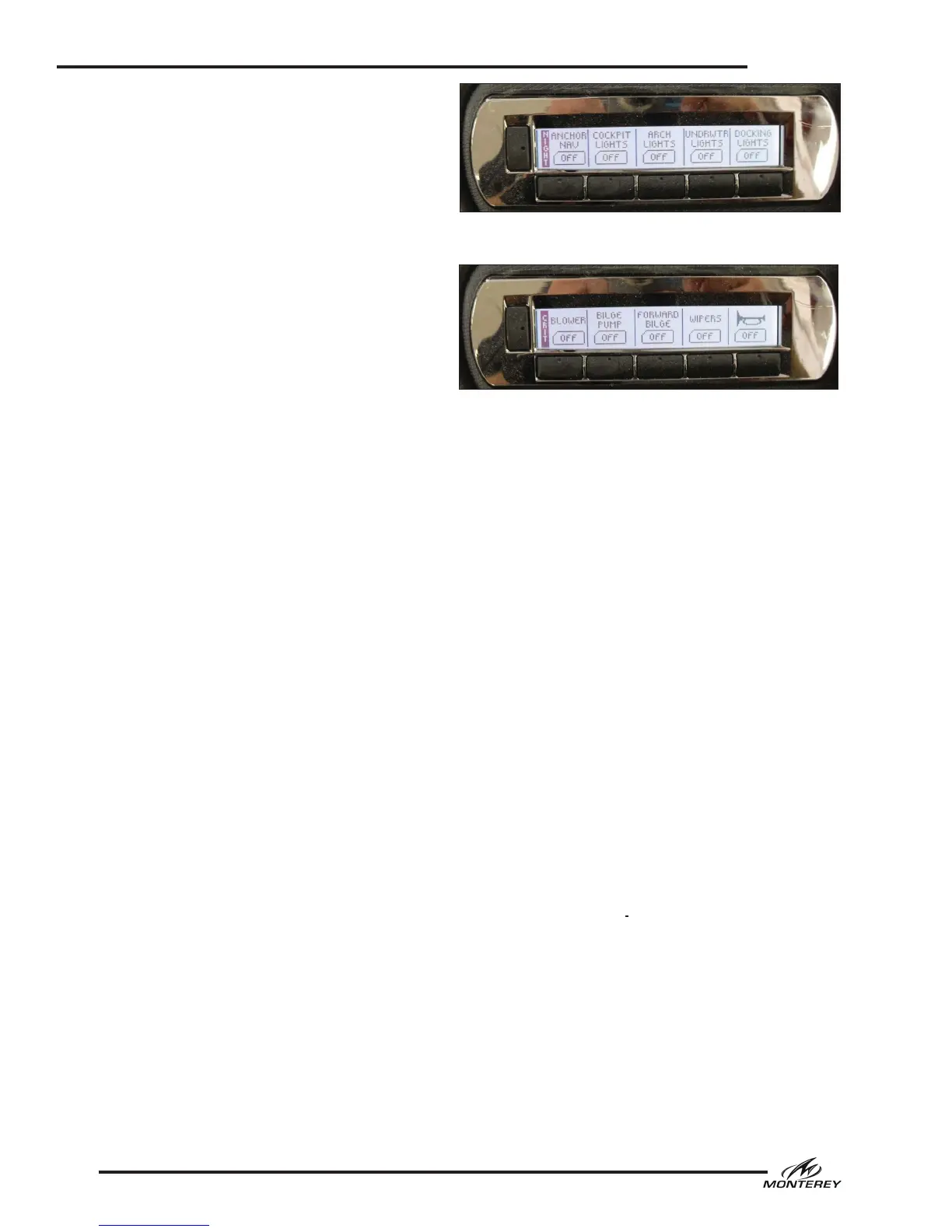
The digital switch modules at the helm are your
interface to the digital system. Each module con-
sists of four pages organized into logical groups.
To change pages, press the vertical button on the
left hand side of each switch module. The system
will scroll to the next page with each press of the
button. LCD labels next to the vertical switches
identify the page. Other LCD labels above each
switch identify the accessories available on that
page. The LCD panels for each switch also indi-
cate switch status, usually ON or OFF. Interior or
cockpit light switches may also indicate the color
of multicolored LED lights activated as well as
their ON or OFF status. All switches are a “press
to activate” and “press to deactivate” design.
Additionally, the port and starboard modules are
set up slightly different. In the interest of safety,
the horn switch is located at the far right of the
starboard switch module and is present in all four
pages so as to be readily accessible at all times.
Other items to note regarding the digital
switching system:
• Most functions are repeated between both
switch modules.
• The switches are turned on and off by the
house battery switch.
• Digital switch module constitute a small drain
on the house battery. Therefore, do not leave
your HOUSE battery switch on for extended
periods of time when the boat is unattended
unless it is boat plugged into shore power with
the battery charger on.
• The port switch module will default to the
and the starboard module will default to the
“Critical” screen.
• The backlights for the gauges are turned on
using the “Anchor Nav” switch. Whenever this
switch is on, the gauges will illuminate.
• Some of the functions shown on the screens
may control optional equipment (i.e. windlass,
exhaust, underwater lights)
• The cockpit lights will alternate between white
and blue each time they are powered on.
Helm Switch Activated Accessories
The following is a description of the accessories
typically controlled by the helm switch panels.
Some of the accessories described in this section
models and may not be installed or available on
your boat.
Ignition Switch
Each ignition switch is a separate, key activated
switch, located near the helm below the steering
wheel, which starts and stops the engine. The
switch has OFF-ON and momentary START posi-
tions. To start the engine, make sure the outdrive
is down and your hand is on the engine control
handle in the neutral position. Turn the ignition
key to the START position. When the engine
starts, release the key and the switch will auto-
matically go to the run position. Stop the engine
by turning the key to the OFF position. The igni-
tion circuits are protected by a breaker located
in the main DC breaker panel and main breakers
located on the engine.
Nav/Anchor Lights
Conventional switches are a three-position switch.
The middle position is “OFF.” Moving the switch
in one direction will activate the navigation lights.
Moving the switch in the opposite direction acti-
vates the anchor light.
Digital switch panels will have a switch for naviga-
tion lights and another switch for the anchor lights.
Docking Lights
Activates the docking lights in the bow.
Critical Page - Digital Switch Panel
Night Page - Digital Switch Panel
 Loading...