29Rev. C, April 2017
TECHNICAL DATA Moog D680 Series Proportional Control Valves
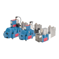
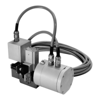
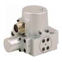
SIZE 08 - D684 PROPORTIONAL VALVE
29
TECHNICAL DATA
Rev. C, April 2017
Moog D680 Series Proportional Control Valves
SIZE 08 - D684 PROPORTIONAL VALVE
Typical Static and Dynamic Data
Valve design 2-stage, with standard
spool
2-stage, with stub shaft
spool
Pilot valve D633
unbiased
1)
D633
biased
2)
D633
unbiased
1)
D633
biased
2)
Step response time for 0 to 100 % stroke 18 ms 26 ms 12 ms 16 ms
Threshold, typical < 0.1 %
Threshold, maximum < 0.2 %
Hysteresis, typical < 0.1 %
Hysteresis, maximum < 0.2 %
Null shift at ΔT = 55 K (131 °F) < 1 %
Sample deviation of rated flow ±10 %
Electrical Data
Duty cycle 100 %
Degree of protection according to IEC/EN 60529 IP65 (with mounted mating plugs)
Supply voltage
5)
24 V
DC
(18 to 32 V
DC
)
Permissible ripple of supply voltage
6)
±3 V
RMS
Maximum current consumption static
7)
0.3 A
Maximum current consumption dynamic
7)
1.2 A
Fuse protection, external, per valve 1.6 A (slow)
EM compatibility • Transient emissions according to EN 61000-6-4
• Emission protection according to EN 61000-6-2
1) Unbiased Pilot Valve for Fail-safe options W
2) Biased Pilot Valve for Fail-safe options D, F, M and U
5) All connected circuits must be isolated from the mains supply by „electrical separation“ in accordance with IEC/EN 61558-1 and
IEC/EN 61558-2-6. Voltages must be limited to the safety extra-low voltage range in accordance with EN 60204-1. We recommend
the use of SELV/PELV power packs.
6) Frequency from 50 Hz to 10 kHz
7) Measured at +25 °C (+77 °F) ambient temperature and 24 V supply voltage