30Rev. C, April 2017
TECHNICAL DATA Moog D680 Series Proportional Control Valves
SIZE 08 - D684 PROPORTIONAL VALVE
30
TECHNICAL DATA
Rev. C, April 2017
Moog D680 Series Proportional Control Valves
SIZE 08 - D684 PROPORTIONAL VALVE
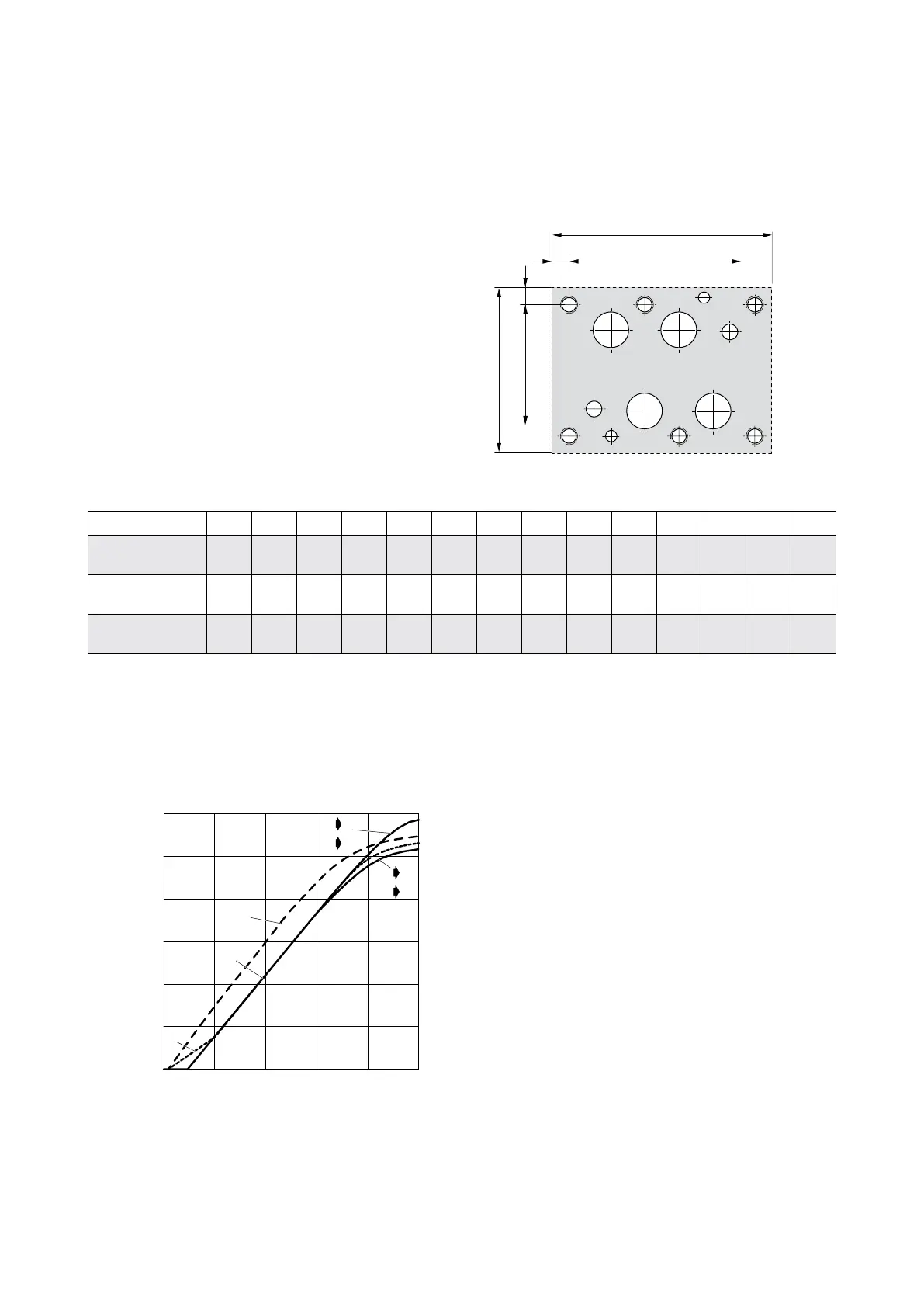
Hole Pattern of Mounting Surface
The mounting manifold must conform to
ISO 4401-08-08-0-05.
• For a maximum flow rate, the ports P, T, A and B should
be provided with a diameter of 32 mm (1.26 in) (not
according to standard).
• Flatness of mounting surface < 0.01 mm (0.0004 in)
over a distance of 100 mm (3.94 in).
• Mean roughness R
a
better than 0.8 µm (0.0000314 in).
Designation P A B T X Y F
1
F
2
F
3
F
4
F
5
F
6
G
1
G
2
Size Ø mm
in
32
1.26
32
1.26
32
1.26
32
1.26
11.2
0.44
11.2
0.44
M12
M12
M12
M12
M12
M12
M12
M12
M12
M12
M12
M12
7.5
0.3
7.5
0.3
Position X mm
in
77
3.031
53.2
2.094
100.8
3.969
29.4
1.157
17.5
0.689
112.7
4.437
0
0
130.2
5.126
130.2
5.126
0
0
53.2
2.094
77
3.031
94.5
3.72
29.4
1.157
Position Y mm
in
17.5
0.689
74.6
2.937
74.6
2.937
17.5
0.689
73
2.874
19
0.748
0
0
0
0
92.1
3.626
92.1
3.626
0
0
92.1
3.626
-4.8
-0.189
92.1
3.626
F
1
F
2
F
5
G
1
F
3
F
6
F
4
G
X
2
A B
P
x
y
Y
T
(6.06)
12
(0.47)
(4.88)
16
(0.63)
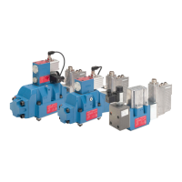
Typical Characteristic Curves
Flow signal curves at Δp
N
= 5 bar (75 psi) per land
D
Y
A
P B
AP
B T
TA
20 40 60 80 1000
N05
P05
500 (132.1)
400 (105.7)
300 (79.3)
200 (52.8)
100 (26.4)
0
Signal [%]
Spool version A: <±3 % overlap, linear flow characteristic
Spool version D: ±10 % overlap, linear characteristic
Spool version Y: <±3 % overlap, dual gain flow characteristic