37 | Top Patch Panel
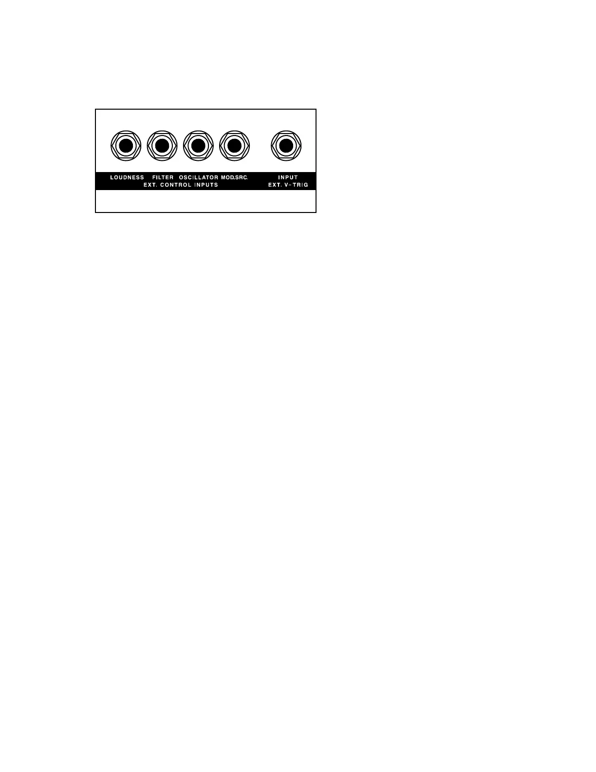
CONTROL INPUTS
LOUDNESS INPUT
A 0 to +5 volt control voltage signal connected to this input jack will aect the overall
level of the Loudness Contour.
FILTER INPUT
A 0 to +5 volt control voltage signal connected to this input jack will aect the Cuto
Frequency of the Filter.
OSCILLATOR INPUT
A 1 V/Octave additive control voltage signal connected to this input jack will aect the
pitch of the Oscillators.
NOTE: The Oscillator, Loudness, and Filter input jacks are equipped with TRS (Tip/Ring/Sleeve)
connectors with a current-limited +5V on the ring. This allows each parameter to be controlled
via control voltage signal or from a Moog EP-3 expression pedal.
MOD. SRC. INPUT
A varying control voltage signal connected to this input jack can be used as a
modulation source. Inserting a standard 1/4” cable into this jack breaks the normalled
connection of the Noise modulation source, and any external control voltage applied
will take its place. With no cable connected, this jack remains normalled, connecting the
Noise send to the MOD. SRC. input, and NOISE can be selected as a modulation source.
TIP: This jack is equipped with a TRS (Tip/Ring/Sleeve) connector, which allows it to also
function as a send for the Noise Generator. With WHITE NOISE selected, the modulation source
becomes Pink Noise. With PINK NOISE selected, the modulation source becomes Red Noise.
EXT. V-TRIG INPUT
This 1/4” jack can receive a standard V-Trigger from other electronic instruments.
It uses a standard V-Trigger connector in place of the S-Trigger and Cinch-Jones
connector used on the original Minimoog Model D. A trigger signal received here
will cause the Contour Generators to fire and will act as a keyboard gate.
Top Patch Panel