EasyManua.ls Logo

Mooney M20K - Page 108

Mooney M20K
437 pages
Print Icon
To Next Page IconTo Next Page
To Previous Page IconTo Previous Page
Loading...
SERVICE
AND
MAINTENANCE
MANUAL
M20K
MOONEY
ArRCRAFT
CORPORATION
C.
Adjust
control
tube
(D)
at
rod
end
(2)
so
that
locknuts
(1)
and
(5)
and
recheck
.020
dimension.
alleron
center
bellcrank
(E)
is
1/16
inch
left
of
center
Repeat
the
operation
on
right
control
wheel
by
tuming
facing
forward
(FIGURE
27-1).
wheel
counterclockwise
until
ailerons
contact
the
D.
Adjust
aileron
control
tubes
(F)
by
removing
stops,
then
proceed
as
described
for
the
left
control
bolt,
nut
and
washer
(4)
(Figure
27-1)
and
loosening
wheel.
Rigging
is
now
complete.
locknut
(6)
(Figure
27-2).
The
aileron
control
tube
(F)
3.
Aileron
Rigging
(S/N
25-0786
ON).
can
then
be
rotated
clockwise
or
counterclockwise
so
A.
Level
control
wheels
(Reference
27-10-00,
3,
that
the
center
of
the
outboard
hole
(K),
(Figure
27-2),
B
procedures).
is
4.3
inches
from
spar
web
(M).
Replace
bolt,
nut
and
B.
Install
3/16
dia
rig-pins
at:
washer
(4),
(Figure
27-1),
and
recheck
4.3
inch
dimen-
(1)Jackshaft
(C)
(Figure
27-1)
sion.
(2)Bellcrank
(E)
(Figure
27-1)
E.
Adjust
aileron
push-pull
tube
(J)
(FIGURE
27-2)
(3)Bellcranks
(9)
(Figure
27-2)
(Both
LH.
and
at
rod
end
(7)
(FIGURE
27-2)
so
that
aileron
tin
neutral
R.H.)
position)
is
0
degree
to
-2
degrees
down
(wah
no
addi-
C.
Adjust
control
tubes
(J)
(Figure
27-2)
(LH.
and
tional
tolerance)
as
measured
with
travel
board
at
wing
R.H.)
to
position
ailerons
at
0
degrees
to
2
degrees
station
indicated
on
travel
board
GSE
030003.
down.
D.
Adjust
remaining
control
tubes
(F),
(B),
(D),
(Figure
27-1)
(1H.
and
R.H.,
if
applicable)
in
order
to
freely
attach
to
the
bellcranks
and
jackshaft.
E.
Remove
n’g-pins.
F.
Adjust
aileron
stops
(Reference
Figure
27-2)
per
paragraph
27-10-00,
3,
F
G.
Tolerances
are
o
specified
in
paragraph
27-10-00,
3,
F.
o
27-20-00
RUDDER
AND
STEERING
SYSTEM
1.
Rudder.
The
rudder
attaches
to
the
aft
vertical
fin
o
spar
at
four
hinge
points.
Push-pull
tubes
and
I
bellcranks
link
the
rudder
to
the
rudder
pedals.
2.
Rudder
Removal
and
Installation.
~T
Bal
Uo
hom.*
Defah
rudder
push-pdl
Ubs
Imn
rudder
B.
Remove
attaching
hardware
at
rudder
hinges.
I
C.
Remove
rudder
by
pulling
it
straight
aft.
D.
Install
rudder
in
reverse
sequence
of
removal.
7j
Recheck
attaching
bolts
for
security
and
safety.
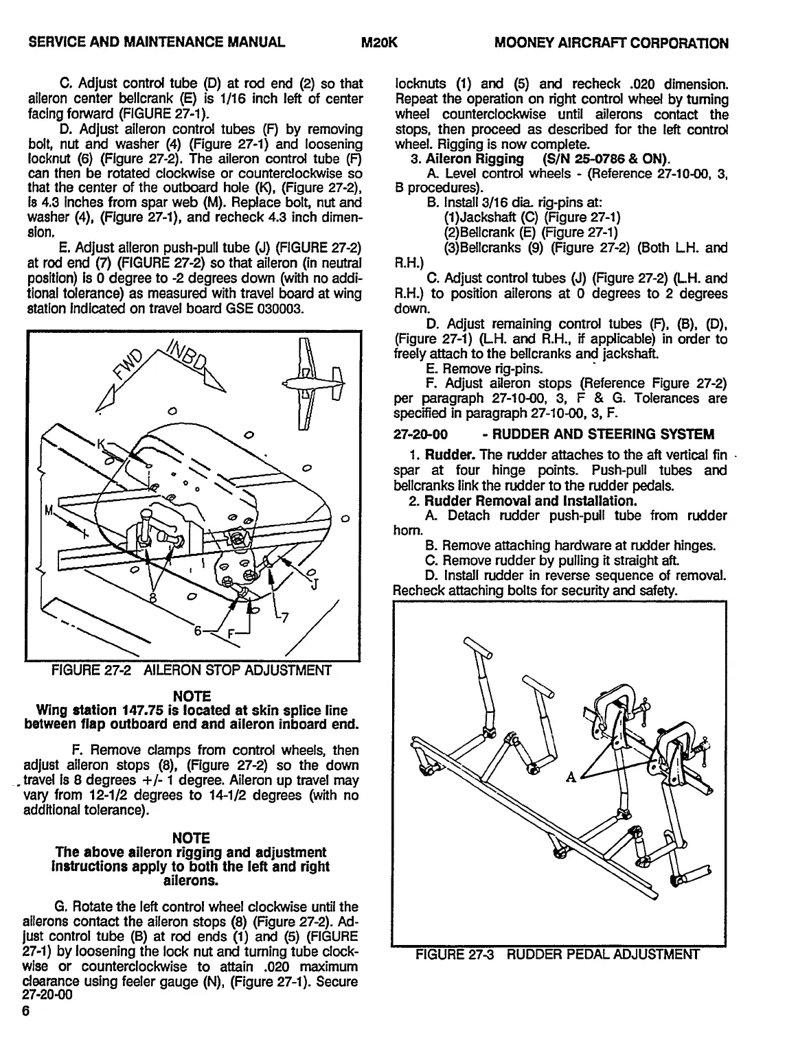
FIGURE27-2
AILERON
STOPADJUSTMENT
NOTE
Wing
station
147.75
is
located
at
skin
splice
line
between
flap
outboard
end
and
aileron
inboard
end.
F.
Remove
clamps
from
control
wheels,
then
adjust
alleron
stops
(8),
(Figure
27-2)
so
the
down
.travel
is
8
degrees
1
degree.
Aileron
up
travel
may
A
vary
from
12-1/2
degrees
to
14-1/2
degrees
(wah
no
additional
tolerance).
NOTE
The
above
aileron
rigging
and
adjustment
instructions
apply
to
both
the
left
and
right
ailerons.
G.
Rotate
the
left
control
wheel
clockwise
until
the
ailerons
contact
the
aileron
stops
(8)
(Figure
27-2).
Ad-
just
control
tube
(6)
at
rod
ends
(1)
and
(5)
(FIGURE
27-1)
by
loosening
the
lock
nut
and
tuming
tube
clock-
FIGURE273
RUDDER
PEDALADJUSTMENT
wise
or
counterclockwise
to
attain
.020
maximum
clearance
using
feeler
gauge
(N),
(Figure
27-1).
Secure
27-20-00
OLDWILLWAYNE

Table of Contents