EasyManua.ls Logo

Mooney M20K - Page 109

Mooney M20K
437 pages
Print Icon
To Next Page IconTo Next Page
To Previous Page IconTo Previous Page
Loading...
MOONEY
AIRCRAFT
CORPORATION
M20K
SERVICE
AND
MAINTENANCE
MANUAL
3.
Rudder
Rigging
and
Adjustment.
A.
Raise
aircraft
nose.
(A
propeller
yoke
jack
may
TRAVEL
BOARD
LDCATIDN
be
used.)
STCL
e550
B.
Set
stabilizer
trim
control
in
neutral
position
r~uvn
BMRD
(stabilizer
parallel
With
aircraff
center
line).
C/L
SKIW
C.
Clamp
pilots
rudder
pedals
(A),
(Figure
27-3),
in
a
RIvn
ROY
neutral
position.
LM1WG
D.
Center
nose
wheel
by
removing
nut,
washer
scREus
bolt
(1),
(Figure
27-4),
and
adjusting
steering
linkage
at
(2).
Bolt,
nut
and
washer
(5)
and
(6)
must
be
installed
laoo
as
shown
from
rear
to
front.
snw
E.
Adjust
control
tube
(C)
at
rear
tailcone
bulkhead
bellcrank,
(Figure
27-5),
and
set
rudder,
by
adjusting
control
tube
(D),
(Figure
27-6),
at
rod
end
bean’ng
(2),
10
to
the
n’ght.
STA.
147.75
NOTE
Rudder
bellcrank,
aft
tailcone,
should
be
TIUML
B[URD
U3CAnPI
BETYEW
FUP
t
AILERPI
modified
per
SINIZO-44.
S1(27-3A
F.
Unclamp
rudder
pedals.
G.
Adjust
rudder
stops
(M),
(F~ure
27-8),
so
that
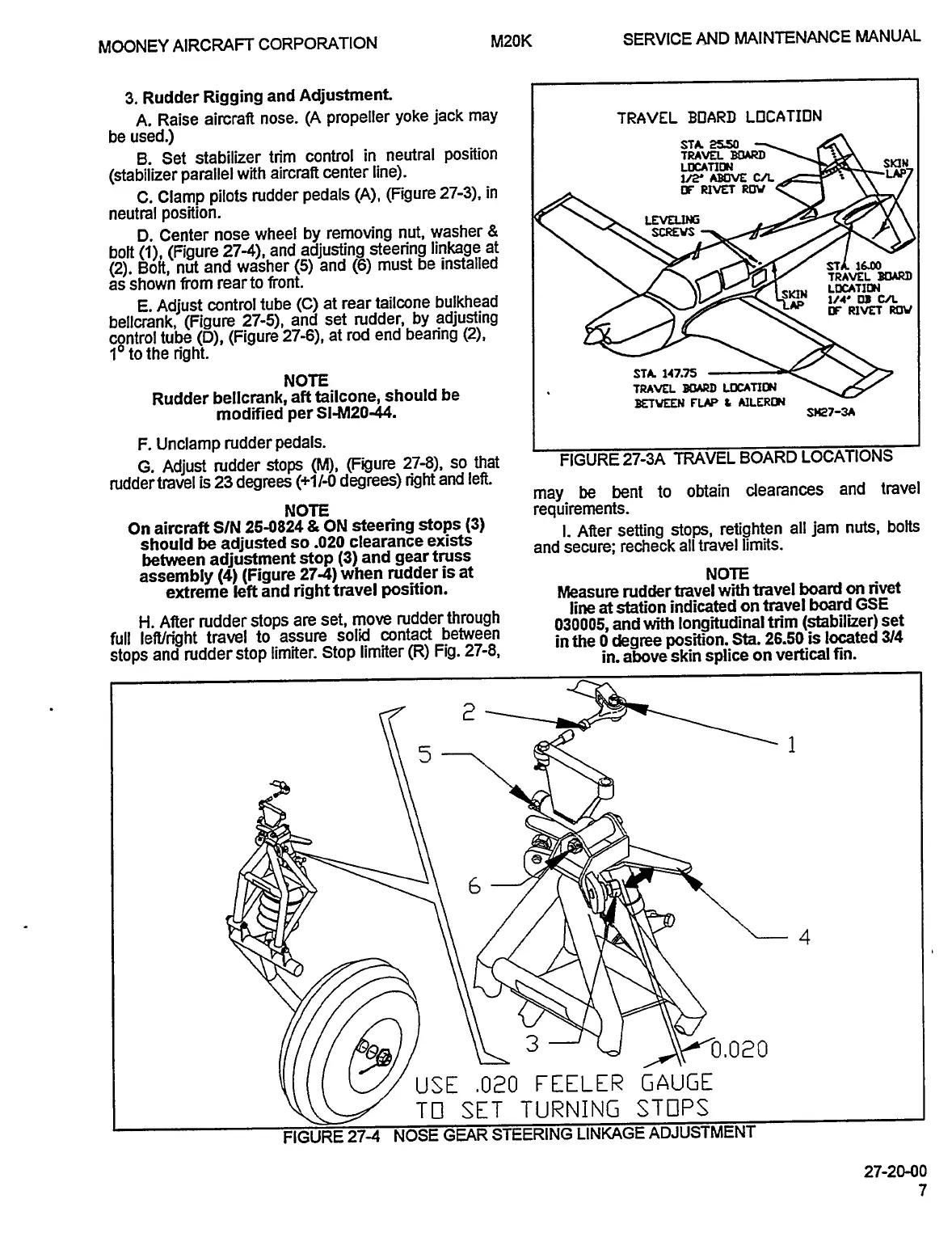
FIGURE
27-3A
TRAVEL
BOARD
LOCATIONS
rudder
travel
is
23
degrees
~1/-0
degrees)
right
and
left.
travel
may
be
bent
to
obtain
clearances
and
NOTE
requirements.
On
aircraft
S/N
25-0824
ON
steering
stops
(3)
i.
After
setting
stops,
retighten
all
jam
nuts,
bolts
should
be
adjusted
so
.020
clearance
exists
and
secure;
recheck
all
travel
limits.
between
adjustment
stop
(3)
and
gear
truss
assembly
(4)
(Figure
274)
when
rudder
is
at
NOTE
extreme
left
and
right
travel
position.
Measure
rudder
travel
with
travel
board
on
rivet
line
at
station
indicated
on
travel
board
GSE
H.
After
rudder
stops
are
set,
move
rudder
through
030005,
and
with
longitudinal
trim
(stabilizer)
set
full
leff/right
travel
to
assure
solid
contact
between
in
the
0
degree
position.
Sta
26.50
is
located
3/4
stops
and
rudder
stop
limiter.
Stop
limiter
(R)
Fig.
27-8,
in.
above
skin
splice
on
vertical
fin.
USE
.020
FEELER
GAUGE
.020
TO
SET
TURNING
STOPS
FIGURE
27-4
NOSE
GEAR
STEERING
LINKAGE
ADJUSTMENT
27-20-00
OLDWILLWAYNE

Table of Contents