EasyManua.ls Logo

Mooney M20K - Page 164

Mooney M20K
437 pages
Print Icon
To Next Page IconTo Next Page
To Previous Page IconTo Previous Page
Loading...
MOONEY
AIRCRAFT
CORPORATION
M20K
SERVICE
AND
MAINTENANCE
MANUAL
M.
Reassembly
brake
cylinder
assembly
and
back
lining
plate
assembly
onto
the
airplane
in
the
reverse
ClcvolMd
sequence
of
disassembly.
75´•1C
Axle
Moun(l~
TLnge
PLIe
Ally.
N.
Bleed
hydraulic
system
as
described
in
Section
12-20-05.
12~
I
O.
Remove
aircraft
from
jacks.
2.
BRAKE
PAD
CONDITIONING
(BREAK
IN)
PROCEDURES.
Wheel
end
tire
RCI~UIL
PII1C
Allcmblr
NOTE
Brake
pad
conditioning
is
required
to
properly
cure
the
resins
binding
the
asbestos
lining
composition
together.
Excessive
heat
created
prior
to
conditioning
will
carbun’ze
the
lining
maten’al
and
prevent
the
attainment
of
1
i/
Brl~e
tyl(ndtr
Proper
conditioning
may
be
accomplished
as
follows:
maximum
braking
coefficient.
A.
Perform
a
minimum
of
six
(6)
light
pedal
effort
braking
applications
and
two
(2)
hard
stops
from
25
to
40
MPH
(21
to
35
KIAS).
Allow
the
brake
discs
to
TORQUE
PLATE
ASSY-CORRECT
RELATION
TO
partially
cool
between
stops.
BRAKE
CYLINDER
The
procedure
will
generate
sufficient
heat
to
cure
resins
in
the
lining,
but
will
not
cause
the
maten’a)
to
wear
of
"0"
ring.
A
scored
brake
cylinder
should
be
become
carburized
due
to
excess’n~e
heat.
replaced.
3.
MASTER
CYLINDER
REMOVAL,
J.
Replace
AN6230-2
"O"
n’ng
(11)
with
a
new
one.
D)SASSEMBLY
and
REASSEMBLY
Do
not
reuse
old
"O"
n’ng.
A.
Remove
left
hand
exhaust
cavity.
K.
Lubricate
cylinder
and
piston
with
Mll-H-5606
B.
Disconnect
hydraulic
cylinder
from
pedal
red
hydraulic
fluid
and
assemble
components
with
care
to
prevent
damage
to
"0"
n’ng,
linkage.
C.
Disconnect
and
cap
hydraulic
lines.
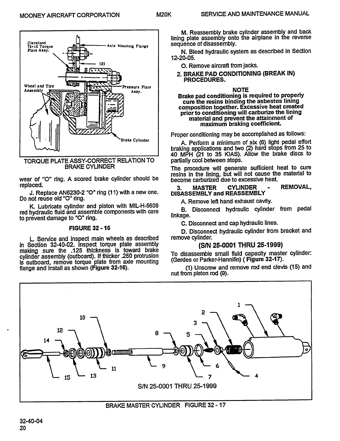
FIGURE
32
-16
D.
Disconnect
hydraulic
cylinder
from
bracket
and
L.
Senrice
and
inspect
main
wheels
as
descn’bed
remove
cylinder.
In
Section
32-40-02.
inspect
torque
plate
assembly
(S~
25-0001
THRU
25-1999)
making
sure
the
.125
thickness
is
toward
brake
cylinder
assembly(outboard)
Ifthicker.250
protrusion
To
disassemble
small
fluid
capacity
master
cylinder:
is
outboard,
remove
torque
plate
from
a~e
mounting
(Gerdes
or
Parker-Hannifin)
Figure
32-111).
flange
and
install
as
shown
(Figure
32-16).
(1)
Unscrew
and
remove
rod
end
clevis
(15)
and
nut
from
piston
rod
(9).
12
8,5
14
9
Lg
15
L
13
7
4
S/N
25-0001
THRU
25-1999
BRAKE
MASTER
CYLINDER
FIGURE
32
17
32-40-04
20
OLDWILLWAYNE

Table of Contents