EasyManua.ls Logo

Mooney M20K - Page 165

Mooney M20K
437 pages
Print Icon
To Next Page IconTo Next Page
To Previous Page IconTo Previous Page
Loading...
SERVICE
AND
MAINTENANCE
MANUAL
M20K
MOONEY
AIRCRAFT
CORPORATION
(2)
Remove
snap
n’ng
(13)
and
lift
out
complete
snap
ring
(2)
from
end
of
piston
rod
piston
rod
assembly,
item
3
thru
12.
(3)
Remove
spacer
(11)
and
O-ring
packings,
(10
(4)
Remove
bushing
(3)
and
spring
(4)
from
end
and
12)
from
piston
and
assembly.
of
piston
rod.
(4)
Disassemble
piston
rod
assembly
by
(5)
Remove
piston
assembly
(5)
and
O-ring
O
removing
roll
pin
(4),
(spring
guide
(3)
will
be
pushed
from
piston
assembly
and
O-n’ng
(6)
from
piston
rod
out
by
spn’ng
(5)
when
roll
pin
is
removed),
spring
(5)
shaft.
and
piston
(7).
(6)
Remove
end
cap
(8)
and
O-n’ngs
(9
[IDD
(7
(5)
Remove
O-n’ng
packing
(6)
from
piston.
[ODD
from
end
cap
assembly.
(6)
Remove
stats-seal
(8)
from
piston
rod.
O
Clean
all
parts
with
cleaning
solvent
(Federal
C~
Clean
all
parts
with
cleaning
solvent
(Federal
Specification
No.
PS661).
Speci~dation
No.
PS-661).
(8)
Inspect
cylinder
for
cracks,
scoring,
or
(8)
Inspect
cylinder
for
cracks,
scon~ng,
or
grooves
in
bore.
grooves
in
bore.
(9)
Inspect
piston
(5)
for
damage,
check
for
nicks
and
scratches.
(9)
inspect
piston
C/)
for
damage,
check
for
nicks
and
scratches
(10)
Inspect
end
cap
(8)
for
damage.
(10)
Inspect
valve
for
damage.
(11)
Inspect
push
rod
for
scon’ng,
grooves,
nicks
and
scratches.
(11)
Inspect
push
rod
for
scoring,
grooves,
nicks
and
scratches.
(12)
Inspect
spn’ng
(4)
for
free
height
.500
in.
+/-.030.
(12)
Inspect
piston
return
springs
(2)
for
permanent
set
and
proper
length
(3.670
in.
mi?.,
4.05
(13)
Replace
all
faulty
parts
and
all
O-rings.
in.max.).
(14)
Reassemble
in
reverse
sequence
of
(13)
Replace
all
faulty
parts
and
all
O-rings.
disassembly.
Immerse
all
parts
in
hydraulic
brake
fluid
(14)
Reassemble
in
reverse
sequence
of
priorto
reassembly.
disassembly.
Immerse
all
parts
in
hydraulic
brake
fluid
(15)
Check
piston
rod
and
return
spring
(13)
for
priorto
reassembly,
proper
compression
dun’ng
stroke
(9
Ibs.
bottom
(S~
25-2000
THRU
25-TEA)
to
32
Ibs.
3/4
stroke)
These
aircraft
have
large
capacity
Master
Cylinders.
F.
Reinstall
master
cylinder
in
reve~se
sequence
of
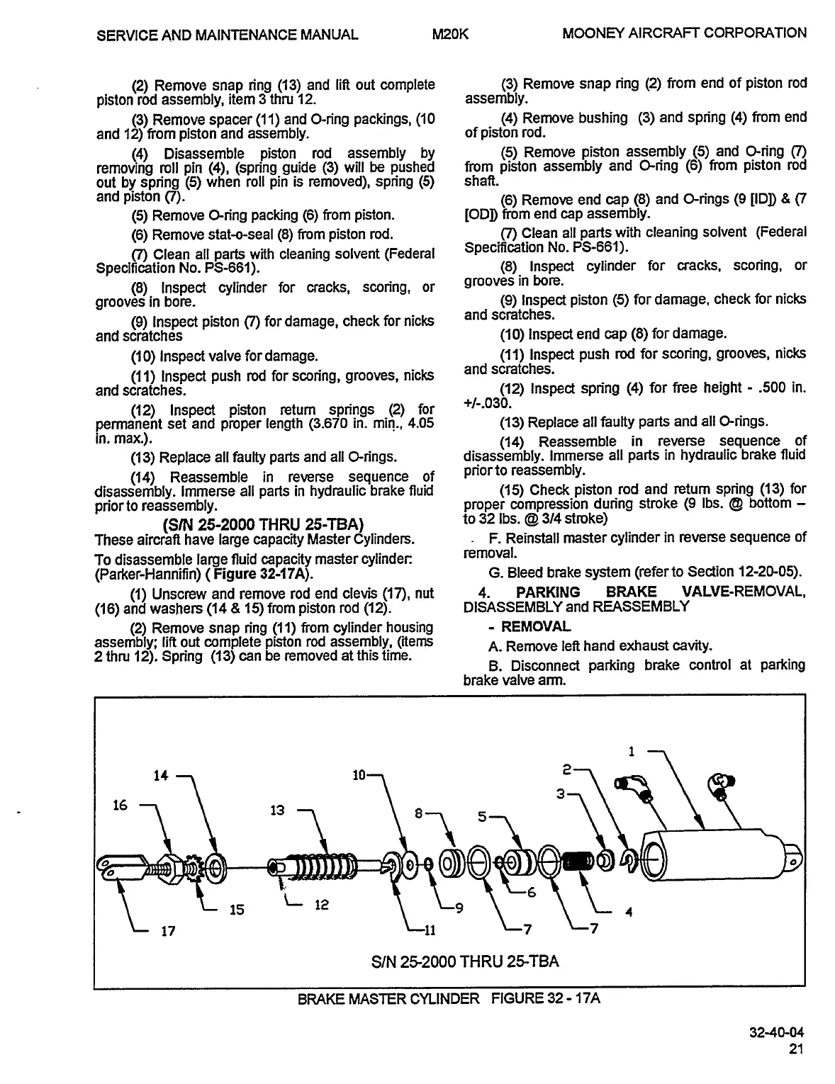
To
disassemble
large
fluid
capacity
master
cylinder:
’emoval.
(Parker-Hannifin)
(Figure
32-17A).
G.
Bleed
brake
system
(referto
Section
12-20-05).
(1)
Unscrew
and
remove
rod
end
clevis
(17),
nut
4.
PARKING
BRAKE
VALVE-REMOVAL,
(16)
and
washers
(14
8
15)from
piston
rod
(12).
DISASSEMBLY
and
REASSEMBLY
(2)
Remove
snap
n’ng
(11)
from
cylinder
housing
REMOVAL
assembly;
lift
out
complete
piston
rod
assembly,
(items
A.
Remove
left
hand
exhaust
cavity.
2
thru
12).
Spn’ng
(13)
can
be
removed
at
this
time.
B.
Disconnect
parking
brake
control
at
parking
brake
valve
arm.
14
1
~"7O
5
15
L
12
17
Lt1
~--7
L7
S/N
252000
’THRU
25TBA
BRAKE
MASTER
CYLINDER
FIGURE
32
17A
32-40-04
OLDWILLWAYNE

Table of Contents