Page 16
TMC-647-(Rev E) - 01/06
MOORE FANS LLC, Marceline, MO 64658 Phone (660 ) 376-3575 FAX (660) 376-2909
120
110
100
90
80
70
60
50
40
30
20
SELECTED BLADE ANGLE
STATIC
PRESSURE
BLADE ANGLE IN DEGREES
1 2 3 4 5 6 7 8 9 10 11 12 13 14 15 16 17 18 19
1.2
1.1
1.0
.9
.8
.7
.6
.5
.4
.3
.2
STATIC PRESSURE
% RATED FAN HORSEPOWER
STATIC PRESSURE
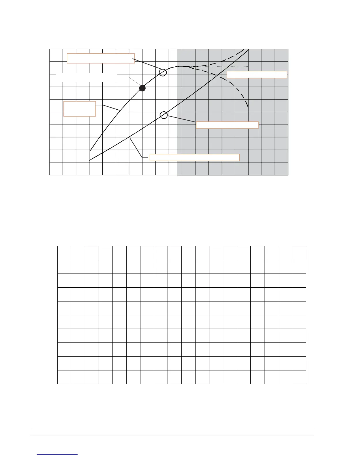
Note in the chart above that static pressure (and air flow) has
reached its maximum at an 11 degree blade setting and blade
overload is beginning. With further increase in blade angle, any-
thing may happen, as indicated by the dotted extensions into the
shaded overload area. Note that the final selected blade angle is
5% below the point where the static pressure curve becomes level.
The horsepower curve has been added to illustrate the point that
in an overload condition, horsepower will increase without in-
creased performance.
BLANK CHART FOR CUSTOMER USE
BLADE ANGLE IN DEGREES
FACTORY-SET BLADE ANGLE
OPERATION
FINAL MOTOR AMPHERES
BLADE ANGLE VS % RATED FAN HP
FULL LOAD
AMPHERES