Page 8
TMC-647-(Rev E) - 01/06
MOORE FANS LLC, Marceline, MO 64658 Phone (660 ) 376-3575 FAX (660) 376-2909
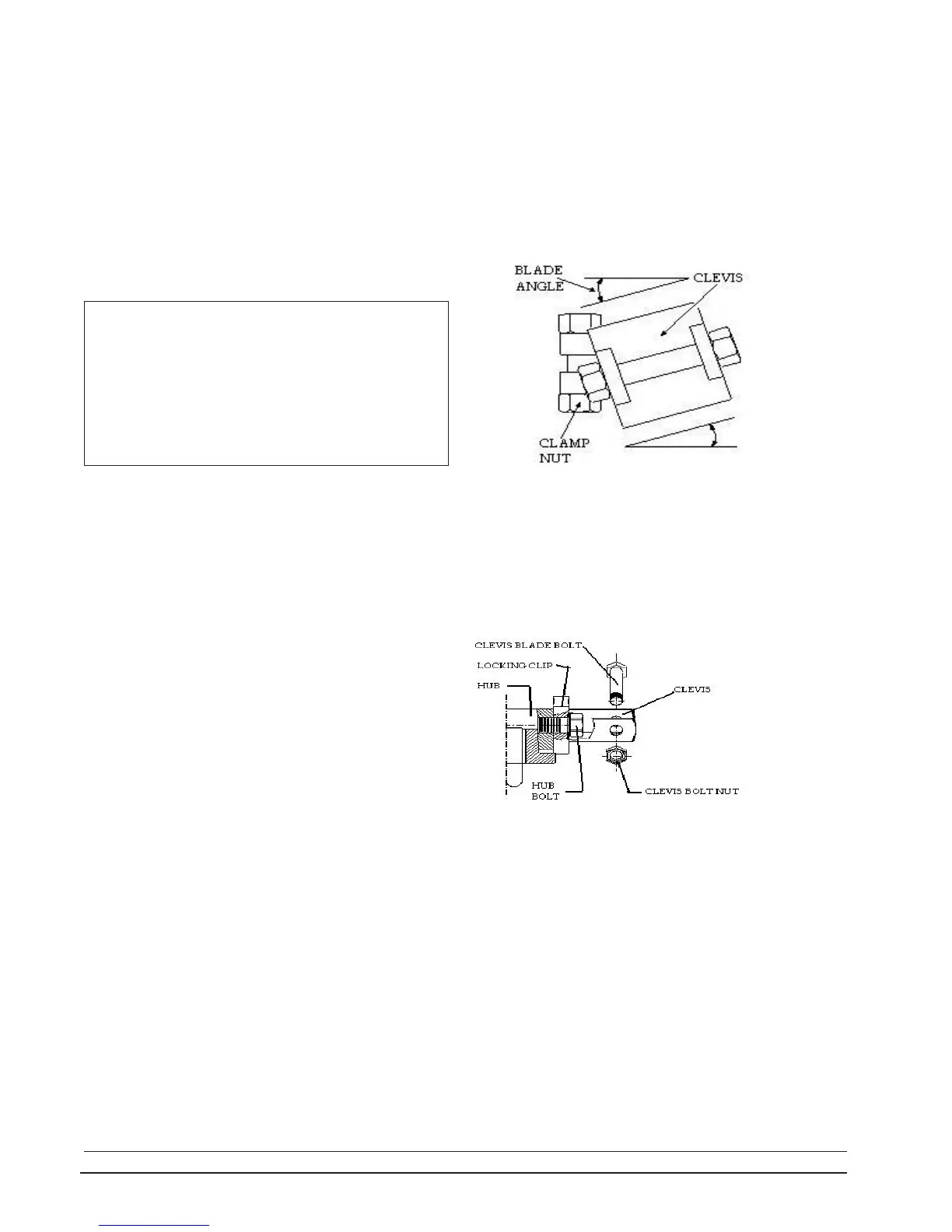
2.5.3 ADJUST BLADE ANGLE (EXCEPT SERIES 19)
Hubs are shipped from the factory with the clevises set
for the blade angle indicated by the design performance. A
change in blade angle is usually necessary, however, to
adjust to actual site conditions. Failure to adjust the blade
angle when required may result in motor overload. To check,
measure the input amps to the motor while the fan is oper-
ating. See Section 2.6 Start-up Procedures below. If the
current draw is higher or lower than desired, slightly de-
crease or increase the blade angle.
blade rotated to one of these two positions.
Place a protractor level on the flat upper or lower
surface of the clevis as shown in the illustration at right. (This
is the point of measurement of the blade angle stated on 1.1
Fan Specifications.) Make a permanent record of the final
NOTE: If the hub is not level, the blade angles will not
be accurately measured. To check, rotate the fan while
checking the angle of a blade. If the measured angle varies
as the fan is rotated, find the two locations, 180
o
apart, where
the angles are identical. Only at these two points will the
angle measured be accurate. Set each blade angle with the
WARNING: The fan is designed to consume the
horsepower stated on the Fan Specification Sheet. This is
not necessarily the full load horsepower of the motor.
Increasing the blade angle to fully load an oversize motor
can cause serious blade overload which will stall the
blades. In this condition, the fan will actually deliver less
air and blade life may be shortened. Blade load consider-
ations are discussed in Section 4.0 Operation in this manual.
2.5.4 ADJUST SERIES 19 BLADE ANGLE
Before starting the fan, manually check all bolts or
nuts to see if they are tightened. Take care not to exceed
the stated torque limits.
Lift each blade to the horizontal position and walk
the blade around while checking for proper clearance.
Start the fan and watch it in operation. All blades
should lift to the same operating position, indicating that
the blade angles are properly set and that all blades are
equally loaded.
If vibration or unbalance is evident, see Section 3.3 in
the following maintenance section.
After the fan has been operating for several minutes,
stop the fan and observe the blades as the fan comes to
rest. All of the blades should fall to their droop position at
the same rate.
Inspect the inner surface of the fan ring and the blade
tips for any indication of scoring.
Check the motor amperage and consult the motor
manufacturer's specification sheet for the actual motor out-
put horsepower for that amperage. The HP given on the
Fan Specifications is the calculated HP (at the fan shaft) that
is required for the specified performance. The motor output
HP may be allowed to be 3% or 5% above the specified fan
HP to allow for gear drive or belt drive losses respectively.
Consult the factory or the fan curve before increasing
the blade angle for the fan to consume more than the speci-
fied HP.
2.6 START-UP PROCEDURES
Read the previous Section 2.5.3 and follow all the
precautions stated. To adjust, remove the blade. Flatten
the tab on the locking clip and loosen the hub bolt just
enough to allow the clevis to be turned. Place a protractor
level on the flat upper side of the clevis and rotate the
clevis in the desired direction. Retighten the hub bolt to 90
to 100 ft-lb (12.5 to 13.8 m-kg) of torque. Recheck the angle
after tightening. Bend one corner of the locking tab against
a flat side of the bolt head to secure the bolt from turning.
Operate the fan and recheck the current draw. Repeat ad-
justment if necessary until amperage readings are as de-
sired.
INSTALLATION
clevis angle selected and take care that all blades on the fan are
set at the same angle. A typical adjustment may be +/- 3
o
.
The maximum recommended clevis angle is 18
o
. For all fans
except Series 19, the blade angle is changed by loosening the
clamp nut, rotating the clevis, and retightening as described
in 2.5.2 above. Torque all clamp nuts to 50 ft-lb (7 m-kg).