MOORE FANS LLC, Marceline, MO 64658 Phone (660 ) 376-3575 FAX (660) 376-2909
Page 7
TMC-647-(Rev E) - 01/06
INSTALLATION
2.5 INSTALL AND ADJUST BLADES
2.5.1 INSTALL BLADES
At times it may be necessary to adjust the fan diameter to suit
a particular ring. To do so, loosen the clamp nut so that the
clevis can be rotated in the hub tube. One complete revolu-
tion of the clevis will increase or decrease the radius of the fan
by .087" (2.2 mm). Take care that the clevis is returned to
exactly the factory-set angle unless it is intended that the
blade loading be changed as discussed in the next section. A
match mark may be made at a point on the threads and the
2.5.2 ADJUST DIAMETER IF REQUIRED
BEFORE INSTALLING BLADES. . . .
Check to see that the hub is level. If the drive shaft is
not truly vertical, causing the hub to be cocked, it will be
difficult to adjust blade angles accurately. Eccentric rota-
tion of the fan can also cause serious vibration problems.
If the fan drive is operational, operate the unit with-
out the blades installed. If misalignment, vibration or un-
balance in the system is present, it will be more easily iden-
tified and corrected at this time.
tube before turning to assure that exactly one revolution is
made. (One-half a rotation is also permissible if carefully done
and the blades are not yet installed.) Tighten the clamp nut to
50 ft-lbs (7 m-kg) torque and repeat the operation on the
balance of the clevises.
Maximum adjustment possible is about +/- .75" (19
mm). At least 1.0" (25 mm) of clevis threads must remain in the
hub tube.
Moore Class 5400 blades are carefully balanced to the same
moment at the factory. Any blade of the same series and
diameter may be installed on any hub furnished on the job.
They are completely interchangeable.
Moore also provides a means of adjusting the fan
diameter on all fans (except Series 19). It is important for fan
performance that the tip clearance — the distance between
the blade tips and the ring — be kept as small as possible.
Install one blade only and adjust the fan diameter if required,
as described in the following section, before proceeding to
install the rest of the blades.
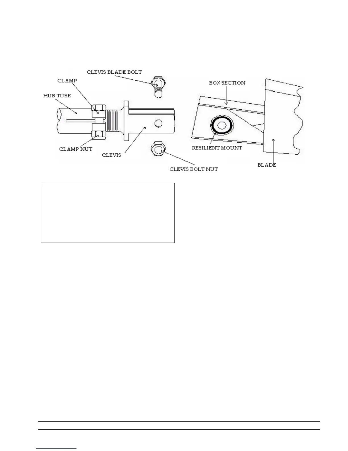
To install, remove the clevis bolt and nut from the clevis
ears. Clean any grease or dirt from inside the clevis ears and
clean the blade resilient mount faces. Align the mount hole
with the holes in the clevis ears and insert the clevis bolt. Screw
the nut onto the projecting bolt threads loosely. When shipped
from the factory, these threads are coated with a special wax.
Be sure this wax is still present on the threads to assure proper
tightening.
Complete the installation of one blade by raising the tip
approximately 1/2 of the way from the stop droop position to
the horizontal position. Holding the blade in this position,
tighten the nut using a torque wrench set to 50 ft-lb (7 m-kg).
Manually rotate the fan while raising and lowering the
blade tip to be sure the blade clears the ring or throat at all
points.When the blade is held in the horizontal position, it
should clear the fan ring by a distance no more than that
required to provide for any relative motion between the fan
wheel and the ring. Adjust as set out in 2.5.2 below until
desired clearance is achieved.
Install the rest of the blades so that they are identical with
the first blade. Torque all clevis nuts to 50 ft-lbs (7 m-kg). If
blades are installed properly, a slight resiliency will be noted
with a spring effect trying to lift the blades from the stop droop
position.