Page 6
TMC-647-(Rev E) - 01/06
MOORE FANS LLC, Marceline, MO 64658 Phone (660 ) 376-3575 FAX (660) 376-2909
2.4.2 FOR AUTOMATIC HUB WITH STANDARD POSITIONER
2.4.3 FOR POSITIONER WITH FAIL LOCKED IN LAST POSITION
Flexible Hose
Installed on
Rotary Union
MAXIMUM SUPPLY PRESSURE:
60 P.S.I. (4.2 Kg/Cm
2
)
Pressure Requirements
Flexible Hoses
Connected to Supply
and Instrument Ports
on Positioner
MAXIMUM SUPPLY PRESSURE:
50 P.S.I. (3.5 Kg/Cm
2
)
0.21 to 1.54
0.42 to 2.24
No. of
Blades
P.S.I.
Kg/Cm
2
3 to 8
9 to 12
3 to 22
6 to 32
2.4.1 FOR AUTOMATIC HUB WITHOUT POSITIONER
Kg/Cm
2
P.S.I.
Control
Supply
3 to 15
(Std)
55
0.21 to 1.05
(Std)
3.9
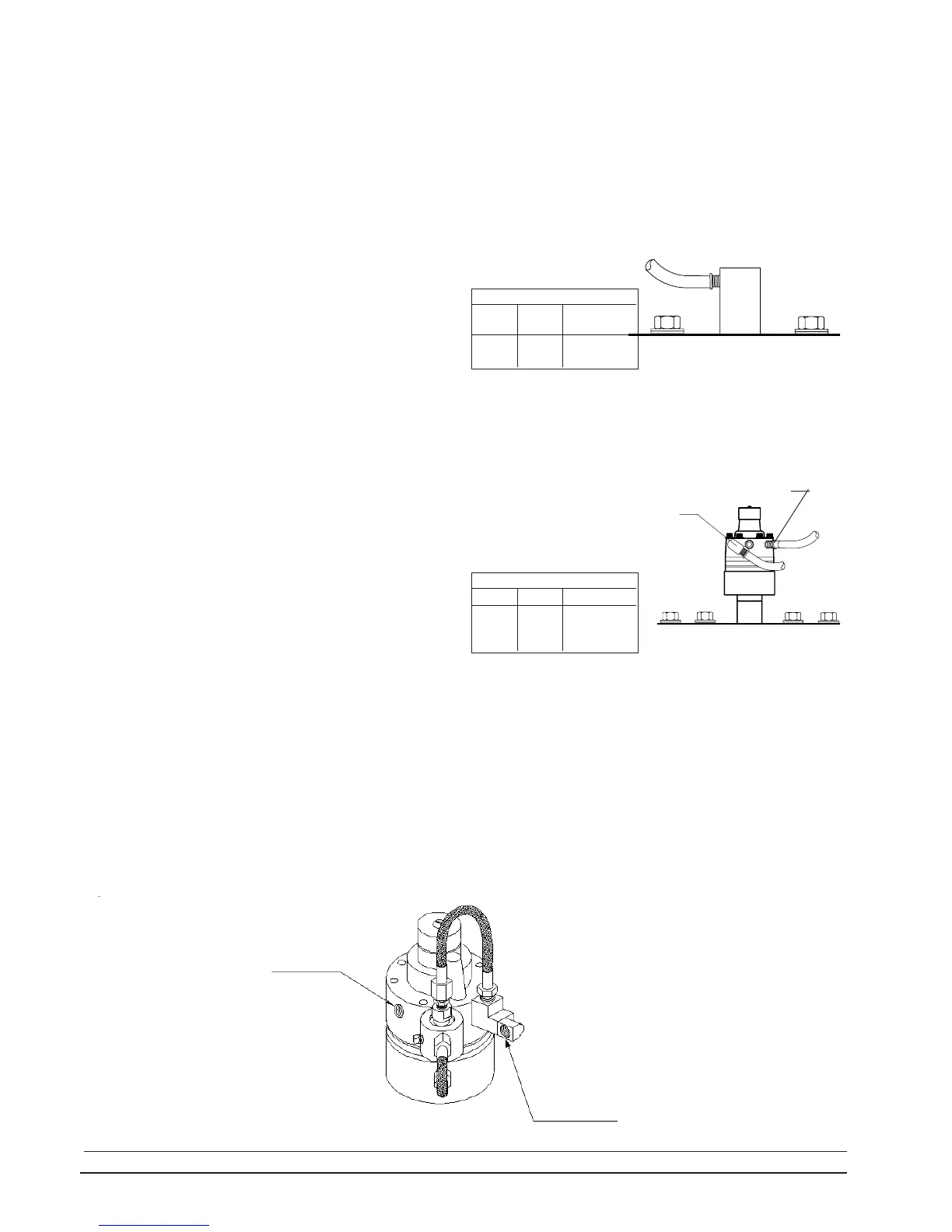
When a fan is specified to fail locked in last position,
pressure is retained in the actuator chamber if the system
pressure falls abruptly. This retained pressure prevents the
blade angle from changing when a failure occurs in the
system supply pressure.
Connect hoses "A" to the instrument port as described
in 2.4.2. Hose "B", which is normally connected to the supply
port is to be connected to the fitting labeled "source air
supply". The flexible hoses provided must be used and a little
slack must be left in them to prevent damage to the bearing or
seal in the rotary union.
When the system is charged, normal pressure at the
valve keeps it in the open position and flow occurs in either
direction between the positioner and the supply actuator. If
the system pressure fails, the valve automatically closes,
retaining pressure in the actuator.
Connect the special flexible hoses provided to the
instrument port "A" and the supply port "B" shown in the
drawing. Use the elbow provided on one hose so that the
hoses will be parallel. Support the positioner while tighten-
ing all fittings to prevent rotary union damage.
The flexible hoses supplied must be used and a slight
amount of slack should be left when connecting to rigid
piping to relieve any abnormal loading of the rotary union
internal bearings and seal.
The ends of the hoses must be capped if not coupled to
the system piping immediately. The flexible hoses provided
terminate in 1/4" N.P.T. male fittings.
A
B
2.4 INSTALL PNEUMATIC TUBING
Connect the flexible hose provided to the rotary union
by threading into the opening. Support the rotary union
while tightening the hose fitting to prevent damage to the
rotary union. The flexible hose must be used. When coupling
to the plant piping, a small amount of slack should be left
to relieve any abnormal loading of the internal bearings
and seals.
If the fan has been specified to fail locked in last
position, the hose is connected to the remote valve piping
rather than directly to the system control pressure and will
function as described in 2.4.3 below.
The hose provided terminates in a 1/4" N.P.T. male
fitting.
INSTRUMENT INPUT
A
SOURCE AIR SUPPLY
INSTALLATION