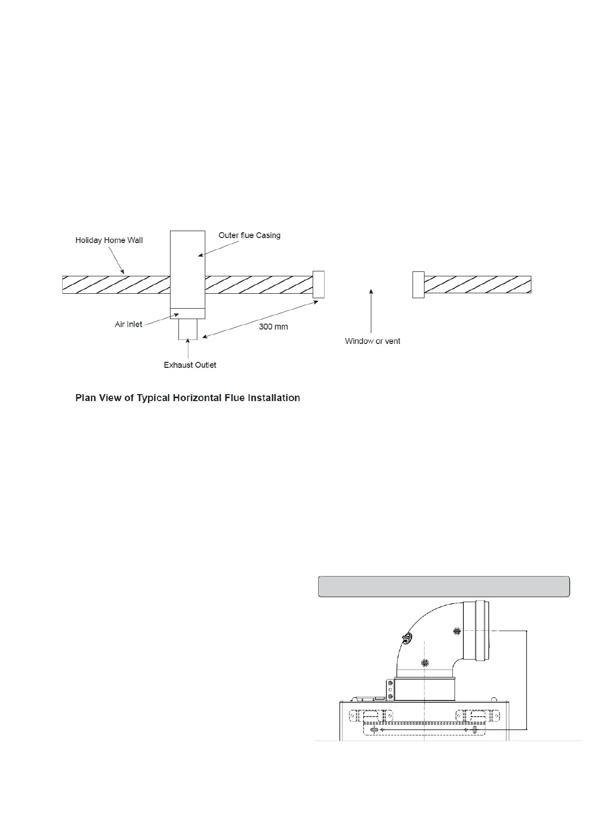
FLUE TERMINAL POSITION
The heater must be installed so that the terminal is exposed to the external air. It is important that the position of the terminal allows
free passage of air across it at all times. It is essential to ensure that the products of combustion discharging from the terminal cannot
re-enter the building or vehicle, through ventilators, windows, or other sources of natural air infiltration, such as other flues etc, with the
exception of doors, but not the opening windows thereof.
The minimum acceptable dimensions from the terminal to obstructions and ventilation openings is as follows:
Directly below an opening fixed vent or window etc ...............300mm
Adjacent to an opening fixed vent or window etc .....................300mm
Below gutters ........................................................................75mm
From a vertical drain pipe ......................................................75mm
From an internal or external corner .......................................300mm
Where the terminal is fitted in a position to which children, the elderly, or disabled people have access (less than 1.5m above steps,
decking or ground), a suitable terminal guard should be fitted. In certain weather conditions the terminal may emit a plume of steam.
Flue - Exhaust Gas and Air Inlet
The appliance can be used with a horizontal or vertical flue system. The respective part codes are RSF503 and RSF545. The Flues
feature concentric tubes, the inner 60mm Ø tube is for the flue exhaust gas and the outer 100mm Ø tube is for the air inlet.
Current flue standards should be adhered to and the flues fitted must be the above supplied by Morco Products as these are CE certified
for use with the appliance.
TYPE C: Horizontal coaxial exhausts
In this configuration, air intake and combustion product exhaust
is outside the home through concentric pipes.
Coaxial exhausts can be faced in the direction most appropriate
to room needs, meeting the methods and lengths indicated
in the following table.
The reference quotas for where to trace wall hole for the
support bracket are provided in figure 10.
TYPE C: Vertical coaxial exhausts
Use the vertical exhaust manifold and, if necessary, the
relevant extensions, observing the maximum admitted lengths
as indicated in the table.
Fig. 10 - Type C exhaust dimensions