ADJUSTMENTS AND MAINTENANCE – FOLDING WHEELCHAIRS | USER MANUAL
23
T 1-866-650-6555 F 1-888-966-6555 E-mail info@motioncomposites.com
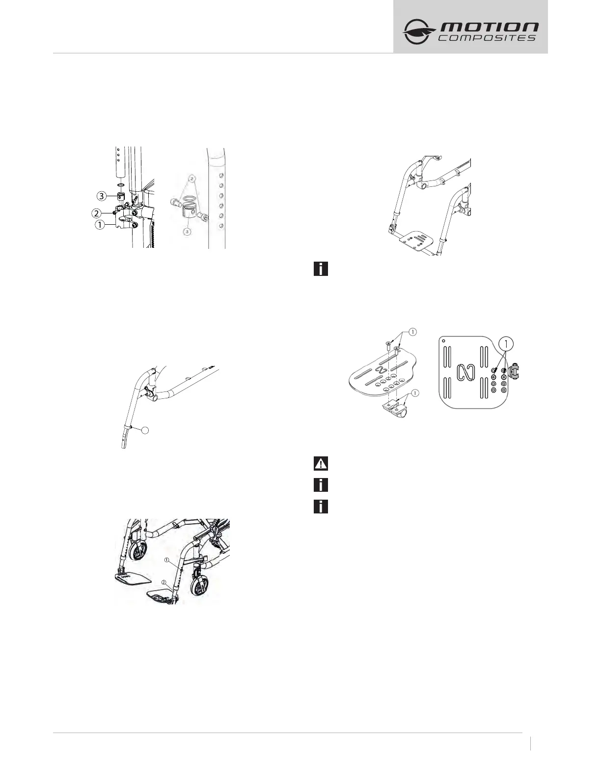
8.6.7 ADJUSTING SWINGAWAY ARMREST HEIGHT
– Pull the armrest out of the receiver (1) (Fig. a).
– Remove screws (2) (Fig. b).
– Inside the armrest tube, slide the dowel nut with a long flat
screwdriver at the desired height (3)
– Reinstall screws (2).
– Reinsert armrest in receiver.
Fig. a Fig. b
8.7 FOOTREST LENGTH / FOOTPLATE ANGLE
8.7.1 ADJUSTING FOOTREST LENGTH
– Loosen screw (1).
– Slide the extension tube inside the front rigging at the desired
length within the limits.
– Tighten screw (1) firmly
.
8.7.2 ADJUSTING FOOTREST LENGTH (SWING AWAY TYPE)
– Remove screws on front riggings (1)
– Slide the extension tube inside the front rigging at the
desired length.
– Reinstall screws (1) at desired length.
– Tighten screws firmly.
8.7.3 ADJUSTING FOOTREST LENGTH
(SINGLE FOOT PLATE TYPE)
– Loosen bottom 5 mm Hex screws (1) on the right and left caster
mount clamps.
– Slide the extension tube inside the front rigging at the desire
length within the limits
– Tighten the screws (1) firmly.
.
ATTENTION
Do not remove or unscrew the security (PIN type)screws.
8.7.4 ADJUSTING FOOTPLATE ANGLE
– Loosen screws (1) (Fig. 24.3).
– Rotate the footplate at the desired angle.
– Tighten screws (1) firmly.
8.7.5 INSTALLING AND ADJUSTING THE LIMB SUPPORT
WARNING
Never sit on an limb support.
INFORMATION
The limb support is not available on the VELOCE model.
INSTALLATION
Installation: refer to the installation of the footrests in point
7.3 Front riggings
– The limb support can be adjusted horizontally from left to right
and up and down for height. It can also be placed closer to or
further from the seat and the angle can be adjusted.
– To adjust the horizontal alignment from the left to right, slightly
loosen the screws (1), slide the cushion horizontally to the
desired position, then tighten the screws at a torque of 7 Nm.
– To adjust the limb support’s angle, slightly loosen the screws
(1), place the cushion at the desired angle and then tighten the
screws at a torque of 7 Nm.
– To adjust the support in relation to the seat, slightly loosen the
screws under the cushion (2), slide the support into the desired
position and then firmly tighten the screws.
– To rotate the base horizontaly, slightly loosen the screws (4)
to to able to rotate the clamp on the main axle. Rotate the limb
support to the right position and firmly tighten the screws in
position at a torque of 7 Nm.
1