ADJUSTMENTS AND MAINTENANCE – FOLDING WHEELCHAIRS | USER MANUAL
27
T 1-866-650-6555 F 1-888-966-6555 E-mail info@motioncomposites.com
WARNINGS
The seat height, seat depth, back angle, seating system/
upholstery, size/position of the rear wheels, size/position
of the front casters, as well as the user condition directly
relate to the stability of the wheelchair. Any change to one
or any combination of the nine may cause the wheelchair to
decrease in stability. These adjustments must be performed
by a qualified technician. Seat-to-floor heights have specific
positions depending on rear wheel size, rear wheel
position, front caster size/position and seat-to-floor angle.
These adjustments MUST be performed by a qualified
technician.
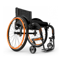
8.11.5 ADJUSTING REAR WHEEL SPACING
– The rear wheels can be adjusted laterally by repositioning axle
bushing (1) on mounting plate (2).
– Loosen nuts (3) on the axle bushing (1).
– Turn the bushing (1) in the desired direction to adjust
the spacing.
– Firmly tighten the nuts (3).
– Nuts can be switched from side to side for more adjustability.
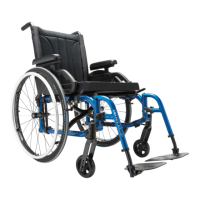
8.11.6 CHANGING REAR CAMBER
MICROADJUSTMENT V2 MOUNTING PLATE
– Note the position of the face plate (4) on mounting plate
– Remove nut (1) and lock washer (2) holding the axle bushing (3)
– Remove axle bushing (3) along face plate (4)
– Change or replace the 3° axle bushing (3)
– Change or replace the 0° or 3° mounting face plate (4) to reach
a 3° or 6° angle
– Reinstall axle bushing, mounting face plate, lock washer and
nut at the desired position on the V2 mounting plate
– Adjust the toe-in / toe-out of the rear wheels
(see section 8.11.5 Adjusting rear wheel spacing)
– Tighten the nut (1) of the mounting plate on the the right and
left side of the wheelchair.
STANDARD T2 MOUNTING PLATE
– Note the position of the axle bushing (3) on the mounting plate
– Remove the 2 nuts (1) and lock washer holding the
axle bushing (3).
– Remove axle bushing (3).
– Change or replace the 3° axle bushing (3).
– Reinstall axle bushing, lock washer and nut at the desired
position on the V2 mounting plate.
– Adjust the toe-in toe-out of the rear wheels (see section 8.11.5).
– Tighten the nut (1) of the mounting plate on the the right and
left side of the wheelchair.
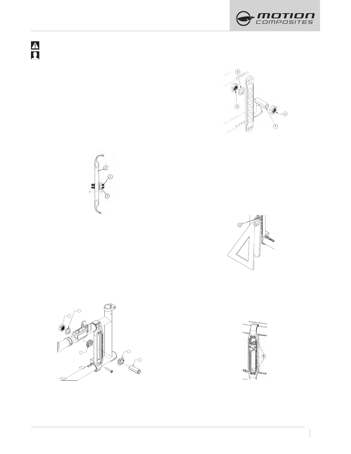
8.11.7 ADJUSTING THE TOEIN/TOEOUT
WITH REAR WHEEL CAMBER
– Remove the rear wheel.
– Maintain the wheelchair on a horizontal plane with the support
of the three other wheels.
– Loosen nuts (1) while keeping a bit of tension.
– Put the camber adjustment tool on the axle bushing.
– Use a set square and rotate the axle bushing so that the tool is
parallel to the set square (and perpendicular to the ground).
– With one hand, hold the tool and the mounting plate together to
keep the setting.
– With the other hand, use a ratchet to tighten firmly the nut (1)
facing inside the wheelchair.
8.11.8 ADJUSTING THE CENTRE OF GRAVITY
– Remove the rear wheel.
MICROADJUSTABLE AXLEPLATE (A7, C2, XC2, VELOCE).
– Remove the 4 bolts (1) on the Axle-Plate.
– Move the axle plate to the desired position.
– Reinstall the 4 bolts (1) on the Axle-Plate and torque
to 12 Nm.
– .
3
1
2
4
4

 Loading...