EN
30
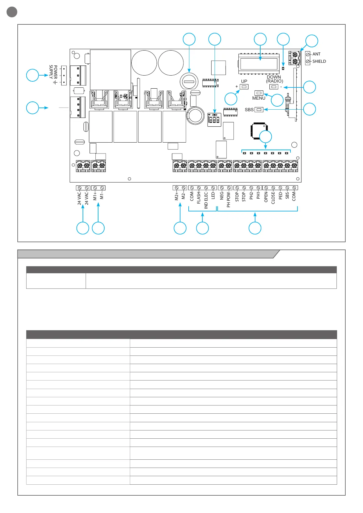
2.5 - Model and technical data of the control unit
TECHNICAL DATA CE24BNC
Power supply (L-N) 230Vac (+10% - 15%) 50/60 Hz
Rated power maximum 210W
Photocell power supply output 24Vdc (without regulation) maximum 250mA
Output for Vac accessories power 24 Vac without regulation 200 mA / 24 Vdc without regulation 250 mA
Flashing light output 24Vdc (without regulation) 15W
Courtesy light output 24Vdc (without regulation) 15W
Electric lock output 12Vac 15VA maximum
Gate open warning light output 24Vdc (without regulation) 5W
Antenna input 50Ω type cable RG58
Operating temperature -20°C + 55°C
Accessory fuses 2AT
Power supply line fuses 1.6AT
Max. number of transmitters storage 150
Use in particularly acid, saline or explosive
atmospheres
NO
Protection class IP54
Control unit dimensions 222 x 110 x 275 mm
Weight 3,93 kg
• Power supply with protection against short-circuits inside the
control unit, on motors and on the connected accessories;
• Obstacle detection;
• Automatic learning of working times;
• Safety device deactivation by means of dip switches: there
is no need to bridge the terminals of safety devices which are
not installed - the function is simply disabled by means of a dip
switch.
Code Description
CE24BNC 24V control unit for two swing gate motors
24 VAC
24 VAC
M1+
M1-
M2+
M2-
COM
FLASH
IND ELEC
LED
NEG
PH POW
STOP
STOP
PH2
PH1
OPEN
CLOSE
SBS
PED
COM
SHIELD
ANT
POWER
SUPPLY
UP
+ -
MENU
SBS
DOWN
(RADIO)
BATTERIES
(BAT371 ACCESSORY)
1 13
2
4
5 3
68 7 15
9
10
12
13
11
14