2
+
4
NC
5
NO
1
-
2
+
1
-
2
+
SEL SET
T.RIT.ANT
T. PAUSA
T.MOT.PED
T.MOTOR
INB.CMD.AP
CODE PED
CODE
AUT/P-P
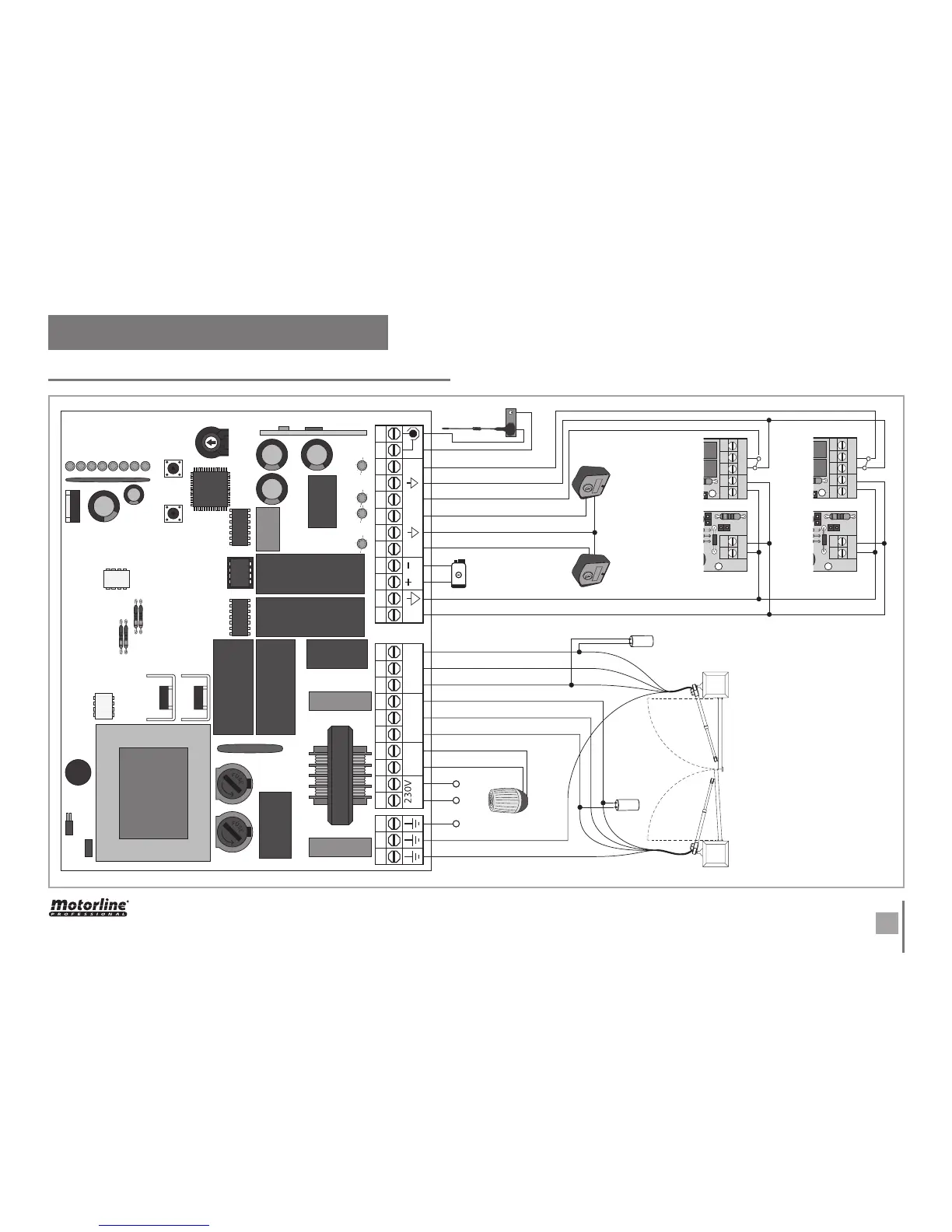
06. CONNECTION SCHEME
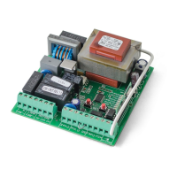
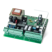
CONTROL BOARD CONNECTION COMPONENT
Interior Photocells
Exterior Photocells
- Motor 1 starts opening before Motor 2 -
- Motor 2 starts closing before Motor 1
- It must be applied an 8μ capacitor in
each motor, on the opening and closing
wires as explained above.
NOTE • If any one of the motors moves in
the wrong way, just switch the brown and
black cables of that motor to change the
direction.
Complete
Opening (2
leaves)
Lock
Light Bulb
Antenna
Earth wire
Black
Brown
Earth wire
Blue
Blue
Brown
Black
Pedestrian
Opening (1
leaf)
Motor 1 Motor 2
- Força +
1D
1D
DS S2
Force
 Loading...