03. CONFIGURATION
EXTENDED MENU 3 CAPACITORS CONNECTION SCHEME
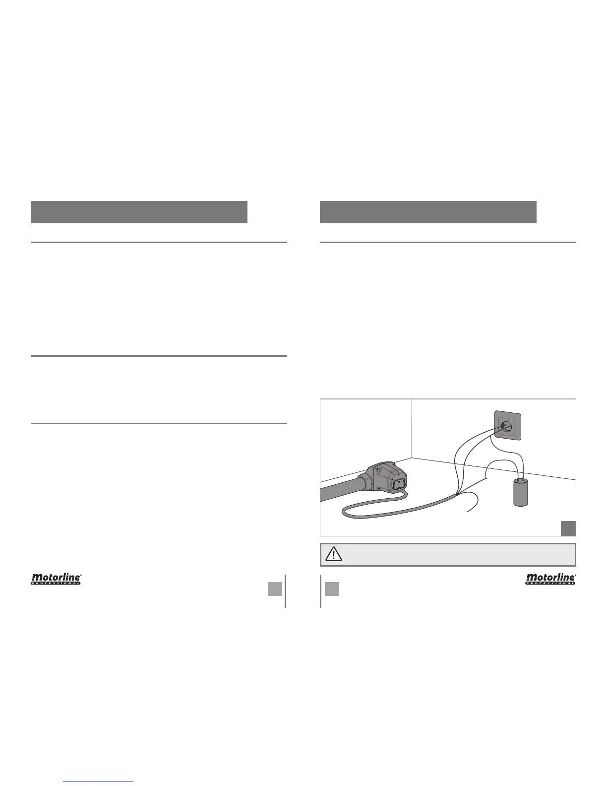
To detect which components have problems on an automated system, sometimes it is
necessary to conduct tests using a direct connection to a 230V AC power supply. For
this it is necessary to merge a 8μF capacitor to make the automation to work. In the
scheme below is shown how this link should be made and how to merge the different
wires of the components.
NOTES:
• To perform these tests you don’t need to remove the automation from where it is
installed, because this way you can know if connected directly to power supply it will
work correctly.
• The order of wiring capacitor to motor wires is not important, as long you connect
one wire to brown wire of motor and the other one to black wire of motor;
• Common wire should always be connected to power supply.
• To reverse motor direction, just replace black wire with brown wire of the operator
on the power supply.
04. COMPONENT TEST
This test only applies to 230V motors. To test a 24V motor, just connect the
motor cables to a 24V battery.
01
If you need to restore central with factory setting, press the SEL and SET buttons si-
multaneously. All LEDs will light up temporarily, and when deleted is confirmed the
success of the operation.
The control board is prepared to a safety device connection in accordance with the sec-
tion 5.1.1.6 of standard EN 12453. In every maneuver is performed a test for the Security
Device and the Lock. In case of a function/connection failure the motor doesn’t start
and every LED’s remain in a intermittent mode, indicating the error. When the photoce-
lls operation is corrected, the control board returns to it’s normal functioning. This ac-
tion by the control board allows to recognize failures in accordance with is mentioned
in category 2 of EN 954-1.
In the position corresponding to each transmitter input in low voltage, the control board
has a LED to identify the condition of it. The LED on indicates that the input is closed,
while the LED off indicates that the input is open.
• PHOTOCELLS TEST
• REMOTE CONTROLS TESTE
PHOTOCELLS AND CONTROLS TEST
RESET TO CONTROL BOARD
CAPACITOR 8μF
AUTOMATION
230V POWER
SUPPLY
Earth wire
Brown
Black
Common (Blue)
Motor power programming during the deceleration:
It is possible to choose up to 6 different levels, relatively the force that the motor per-
forms in deceleration. The levels are represented by combinations of the LED indicated
in the table above.
Scroll through the LEDs with the SEL button to set the desired power, knowing that the
LED AUT / P-P. ON corresponds to minimum power, while the LEDs AUT / P-P., CODE,
CODE PED, INB. CMD. AP, T. MOT., T. MOT. PED ON corresponds to maximum power.
The control board is supplied by the manufacturer with the power regulated at level 3
(AUT / P-P., CODE, CODE PED ON).
 Loading...