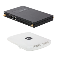
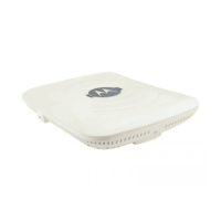
12 AP6532 Access Point
2. Plug the Ethernet cable into the unit and to a controller with an 802.3af compatible power source.
3. Align the bottom of the T-bar with the back of the case.
4. Orient the case by its length, and the length of the T-bar.
5. Rotate the case 45 degrees clockwise, or about 10 o’clock.
6. Push the back of the case onto the bottom of the T-bar.
7. Rotate the case 45 degrees counter-clockwise. The clips click as they fasten to the T-bar.
8. Verify the unit has power by observing the LEDs.
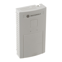
2.6 External Antenna Model Wall Mount Instructions
Wall mounting requires hanging the AP6532 Access Point along its width or length using the pair of slots on the
bottom of the unit. The AP6532 can be mounted onto any plaster, wood, or cement wall surface using the provided
wall anchors. The following illustration shows a lengthwise mount.
2.6.1 Wall Mount Hardware
• Two wide-shoulder Phillips pan head self-tapping screws
• Two wall anchors
• Safety wire (recommended) and security cable (optional)
NOTE In the event the original mounting screws are lost, the following screws
can be used: (ANSI Standard) #6-18 X 0.875in. Type A or AB Self-Tapping
Screw, or (ANSI Standard Metric) M3.5 X 0.6 X 20mm Type D
Self-Tapping Screw.
 Loading...