Installation Guide 13
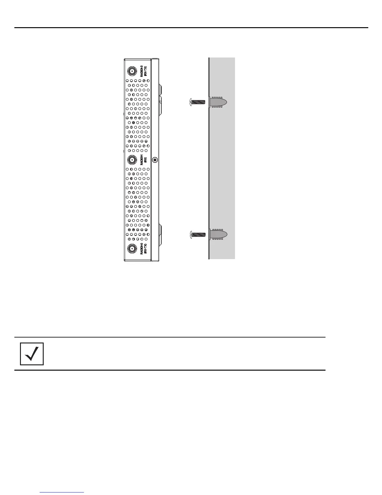
2.6.2 Wall Mount Procedure
1. Orient the case on the wall by its width or length.
2. Using the arrows on one edge of the case as guides, move the edge to the midline of the mounting area and
mark points on the midline for the screws.
3. At each point, drill a hole in the wall, insert an anchor, screw into the anchor the wall mounting screw and
stop when there is 1mm between the screw head and the wall.
4. If required, loop a safety wire, between 1.5mm (.06in.) and 2.5mm (.10in.) in diameter, around the tie post and
secure the loop.
5. If required, install and attach a security cable to the unit’s lock port.
6. Place the large corner of each of the case’s mount slots over the screw heads.
7. Slide the case down along the mounting surface to hang the mount slots on the screw heads.
8. Attach appropriate antennas to the connectors.
9. Attach the Ethernet cable to the unit and to a controller with an 802.3af compatible power source.
10. Verify the unit has power by observing that the LEDs are lit or flashing.
NOTE The recommended hole size is 2.8mm (0.11in.) if the screws are going
directly into the wall, and 6mm (0.23in.) if the provided wall anchors are
being used.
 Loading...