3-2 Basic Theory of Operation: Analog Mode of Operation
3.2 Analog Mode of Operation
This section provides an overview of the analog mode receive and transmit theory of operation.
3.2.1 Receiving
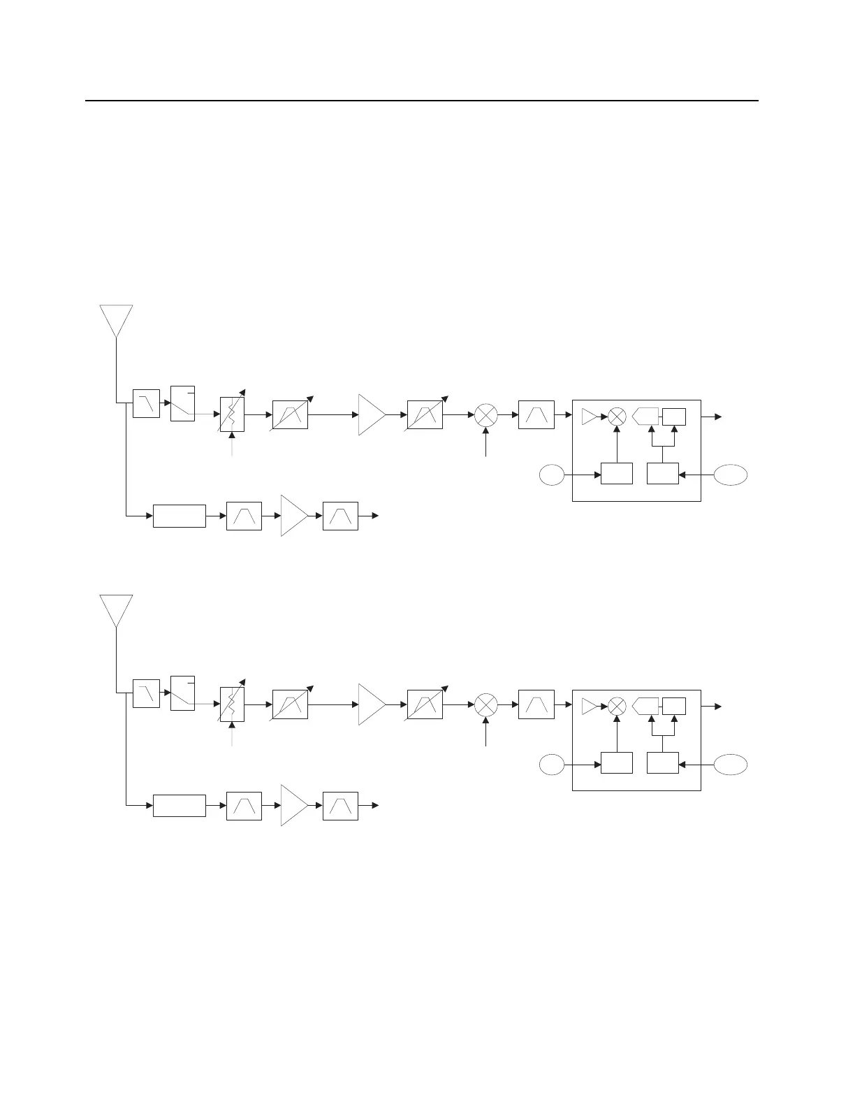
The RF signal is received at the antenna and is routed through the Harmonic Filter, followed by the Antenna
Switch and finally the 15dB Step Attenuator IC. The latter contains a switchable attenuator that is enabled at
predetermined RF power thresholds present at the antenna port. See,
Figure 3-2, Figure 3-3, Figure 3-4 and
Figure 3-5.
Figure 3-2. Receiver Block Diagram (UHF1)
Figure 3-3. Receiver Block Diagram (UHF2)
Antenna
Switch
15 dB Step
Attenuator
UHF1 UHF1
IF Filter
DIG_CTRL_ATTH Rx LO
To GPS
Diplexer
SSI
18Mhz
CLK
Abacus III
ABACUS III
Dec.
Filter
ΣΔ ADC
2nd
LO
LO CLK
Antenna
Switch
15 dB Step
Attenuator
UHF2 UHF2
IF Filter
DIG_CTRL_ATTH Rx LO
To GPS
Diplexer
SSI
18Mhz
CLK
Abacus III
ABACUS III
Dec.
Filter
ΣΔ ADC
2nd
LO
LO CLK

 Loading...


