xviii ASTRO APX 2000/ APX 4000 (Two Knobs) 700/800 MHz Model Chart (Continued)
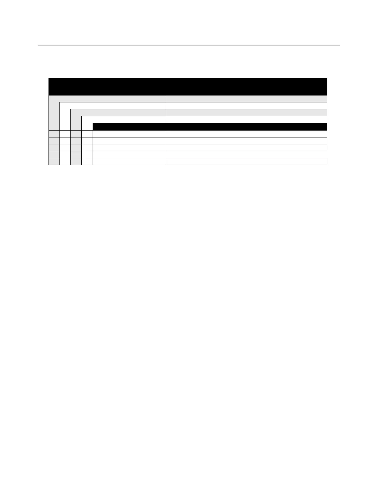
ASTRO APX 2000/ APX 4000 (Two Knobs) 700/800 MHz Model Chart
(Continued)
MODEL DESCRIPTION:
FCC ID:
764–870 MHz,APX 4000_2000
AZ489FT7049
H51UCF9PW6AN APX 4000 Model 2 7/800
H52UCF9PW6AN APX 2000 Model 2 7/800
H51UCH9PW7AN APX 4000 Model 3 7/800
H52UCH9PW7AN APX 2000 Model 3 7/800
ITEM NUMBER DESCRIPTION
●●●● HN000161A01 Bezel, Top Control (Yellow)
●●●● HN000161A02 Bezel, Top Control (Black)
●●●● HN000164A01 Accessory-Connector Cover, Yellow
●●●● HN000164A02 Accessory-Connector Cover, Black
XXXX PMLN5997_ User Guide CD, APX2000 and APX4000
Note:
X = Item Included.
• Option available. Can be serviced in depot and ordered thru AAD.
O Option available. Can be serviced in depot and orderable by UL qualified customers/dealers only. For APAC – Only UL label can be
replaced and purchased by Motorola.
• Refer
Appendix A for antennas, batteries and other applicable accessories.
* The radio’s model number and FLASHcode are required when placing an order for the Main Board.
• The model number and (sometimes) the FLASHcode can be found on the FCC label on the back of the radio.
• The model number and the FLASHcode can be found by putting a Model 1.5, 2 or 3 radio into the Test Mode.
• The model number and FLASHcode can be found by using the Programming Cable (PMKN4012B or PMKN4013C) and
the CPS to read a Model 1.5, II, or III radio.

 Loading...